Build Guide - PCB Assembly
 
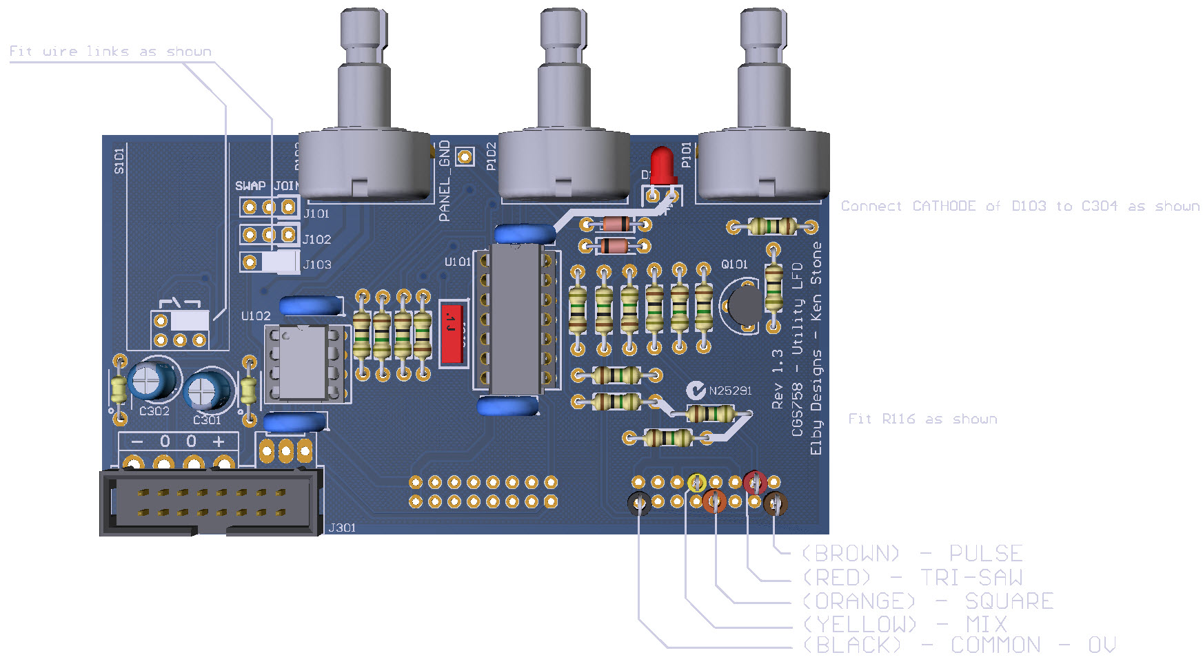
3D Model
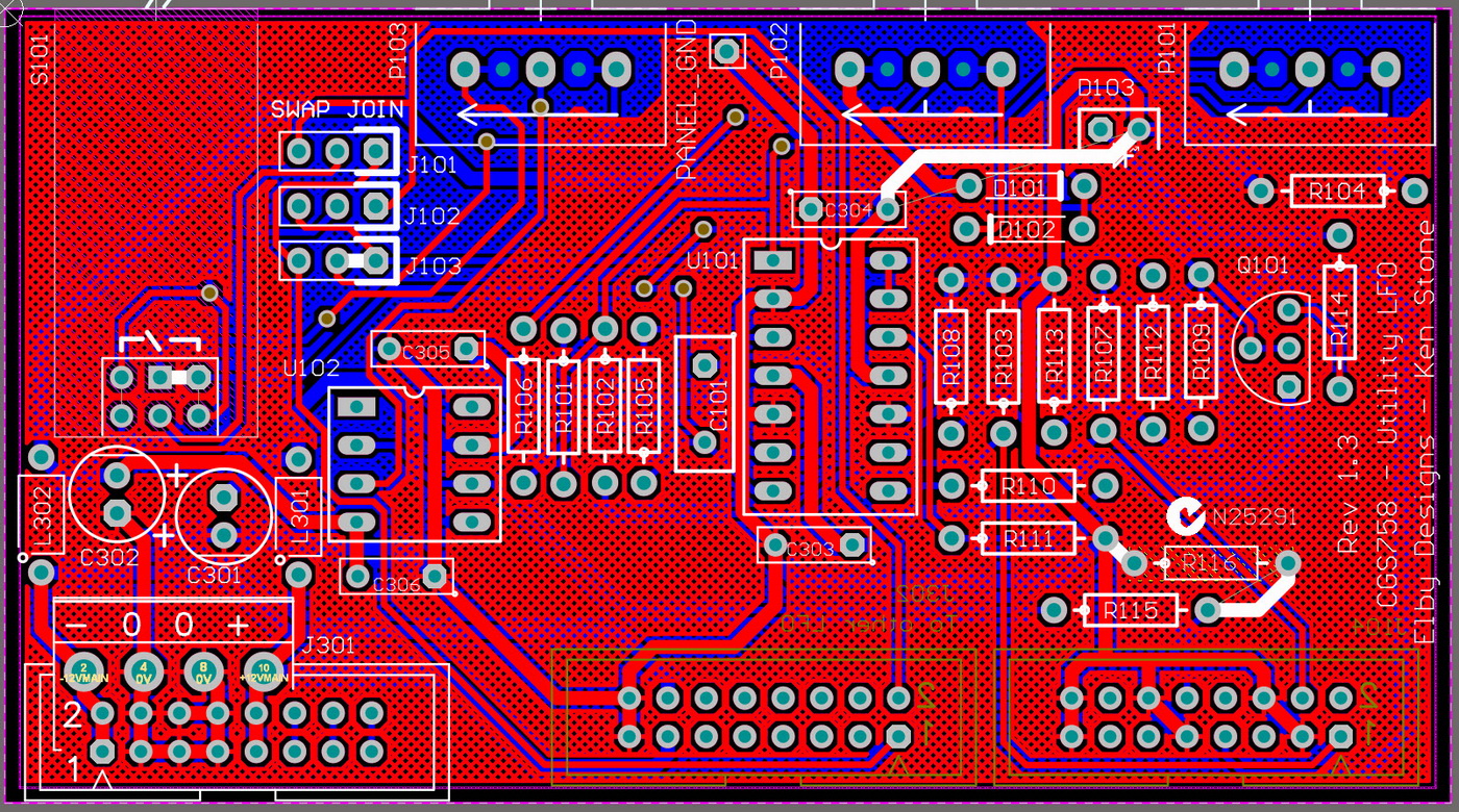
Overlay
Plan View

Constructors should refer to the Component Overlays along with,
the Bill of Materials for the current value of all components, and
the General Construction Notes for general PCB assembly guidelines.

  1. Start by preparing the LED as per the instructions in the General Construction Notes with the exception that the black lead should be cut 2cm longer than the red lead.
  2. Fit the LED lens to the front panel
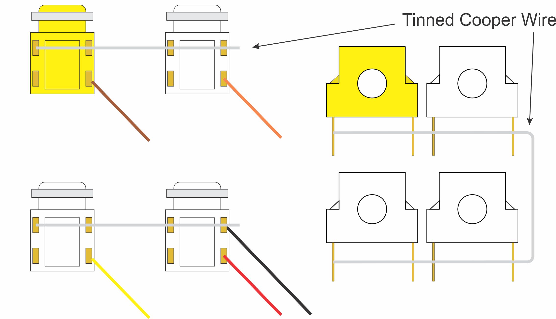
  3. Mount the [PULSE] and [SQUARE] jacks on to the front panel with their legs pointing to the right-hand edge of the panel
  4. Solder the tinned copper wire across the 4 legs nearest to the panel and fold the excess wire up
  5. Mount the [TRI-SAW] and [MIX] jacks on to the front panel, again with their legs pointing to the right-hand edge of the panel
  6. Fold the tinned copper wire across the 4 legs nearest to the panel
  7. Solder the 5 lengths of equipment wire to the indicated pads on the jacks
  8. Mount all components on to the PCB except for the LED
  9. Offer the assembly up to the front panel and secure using the supplied nuts and washers
  10. Solder the sub-assemblies in to place
  11. Install the LED by inserting the red lead in to the left pad of D103. Solder the black lead to the right pad of C304.


Email:  elby-designs@bigpond.com
© Copyright 2000. All rights reserved.     Revised: March 14, 2025