| |
| |
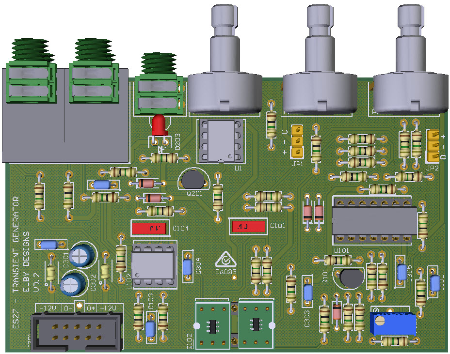
3D Model |
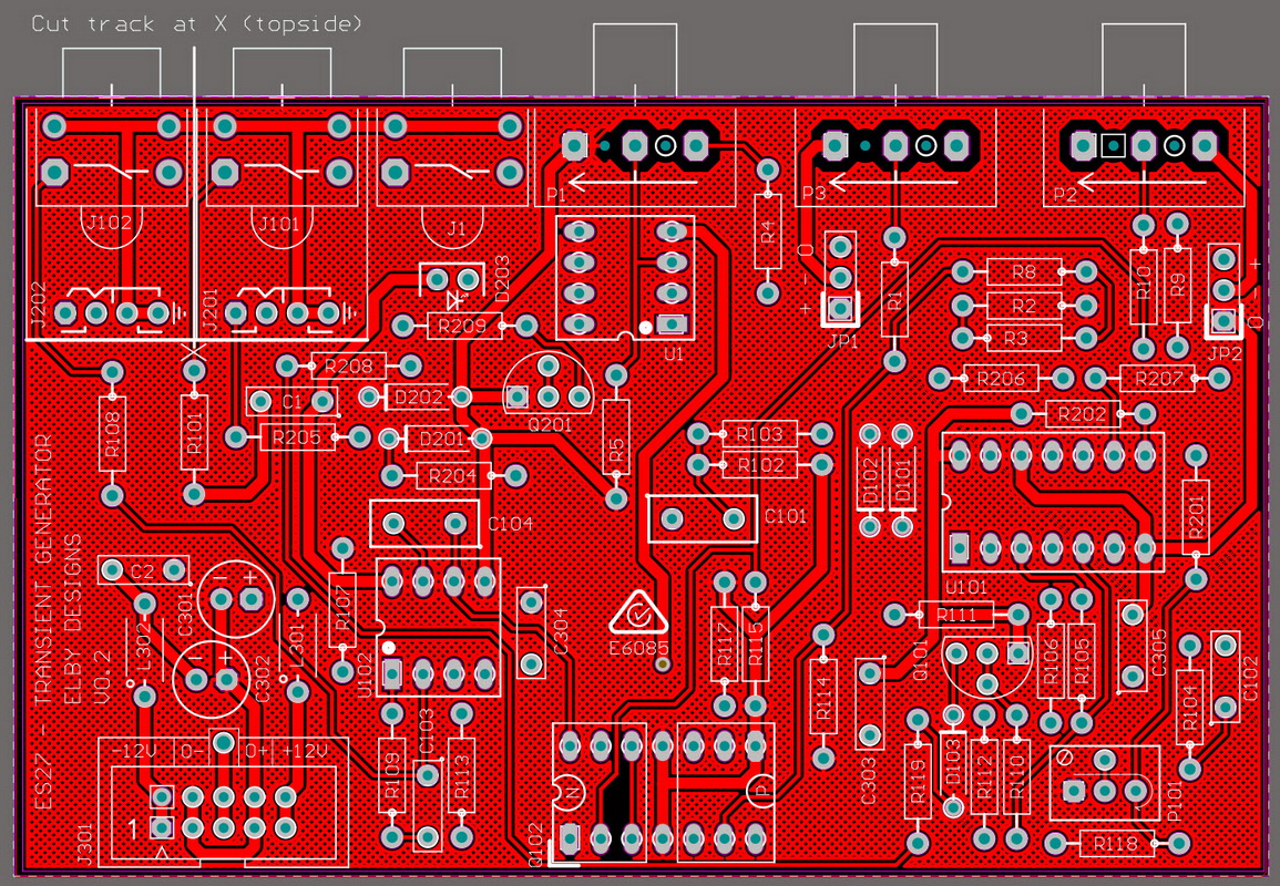
Overlay |
Plan View |
|
|
|
|
Constructors should refer to the Component Overlays along with,
the Bill of Materials 3.5mm 4mm for the current value of all components, and
the General Construction Notes for general PCB assembly guidelines.
- Fit the lens mount to the front panel
- Assemble 2x Jack Carrier Boards
- Prepare the LED as per General Construction Notes
- If not already done by ELBY Designs, cut the track to R101 as shown on the overlay.
- Fit all components to the PCB except for the Jack Carrier sub-assemblies, J101, J102 and the LED
- Strip, twist and tin approximately 1mm of one end of each of the 3 wires
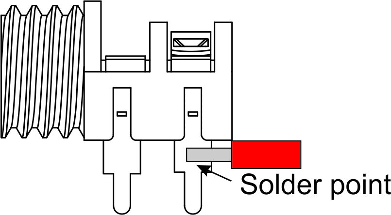
- Carefully solder the red wire to the 'signal' contact of the red jack (J101)
- Mount the Jack Carrier sub-assemblies but do not solder
- Feed the red wire through one of the unused holes on the J101 Jack Carrier assembly
- Offer the assembly up to the front panel and secure using the supplied nuts
- Solder the Jack Carrier sub-assemblies in to place
- Mount the switch S101 and secure using the supplied nuts and washers
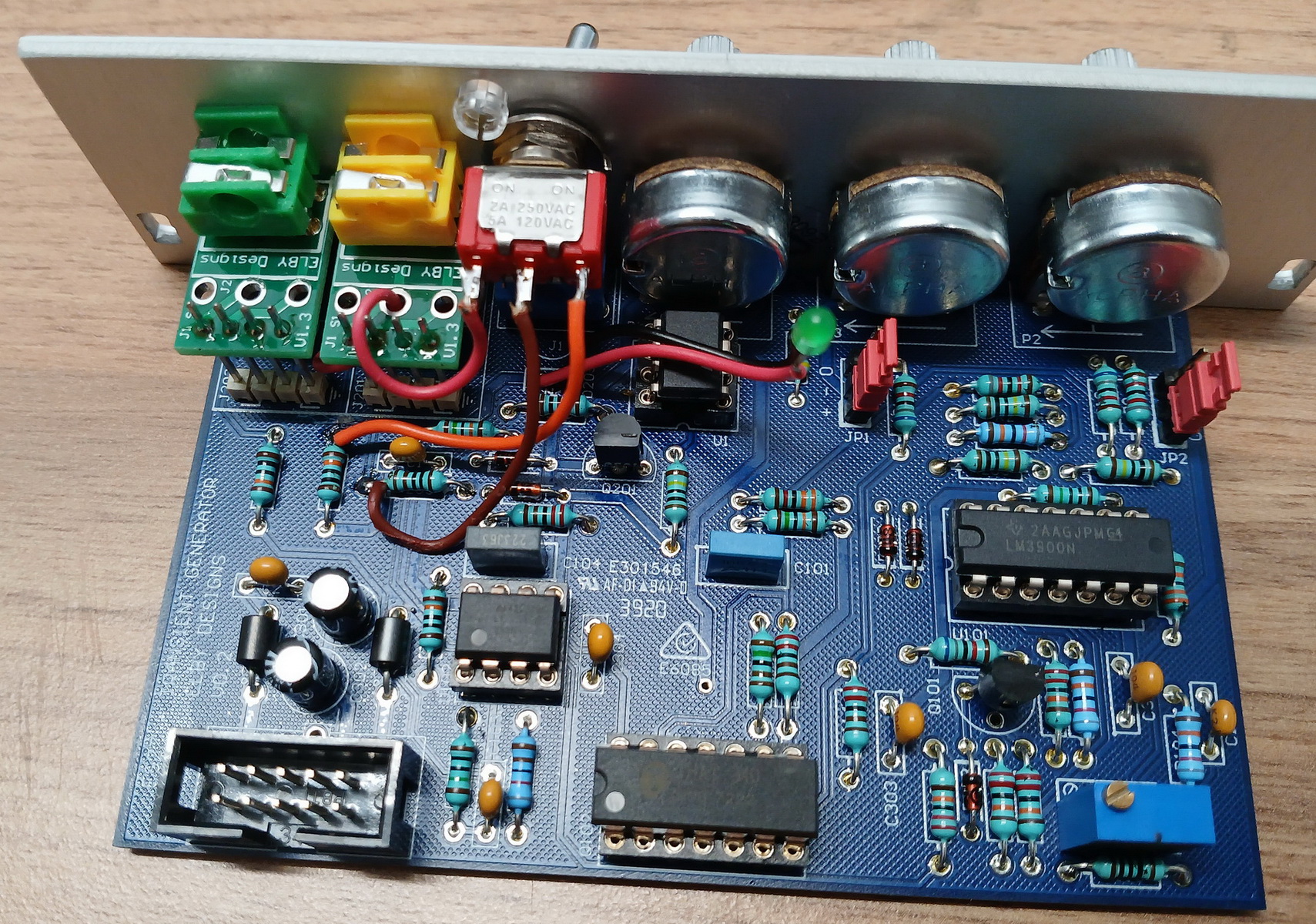
- Solder the orange wire to the top pad of R101 and the brown wire to the left pad of R205
- Cut the wires to a suitable length to terminate on switch S101. Strip, twist and tin approximately 2mm off each wire and then solder to S101
- Feed the LED wires in to their respective pads, mount the LED in to its lens mount and solder into position
|
|
|