|
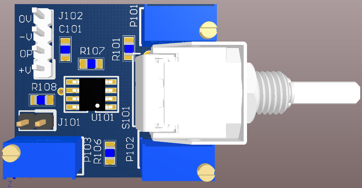
3D Model

|
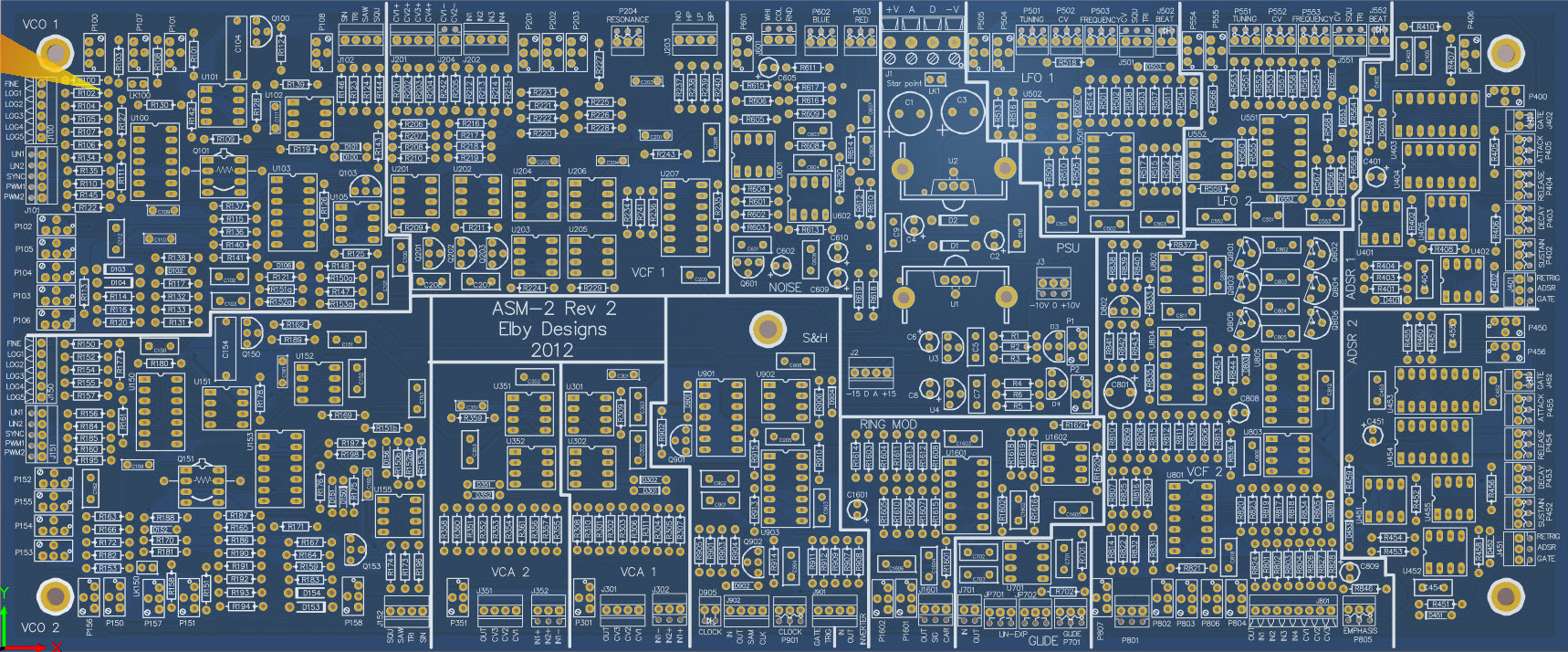
Overlay
|
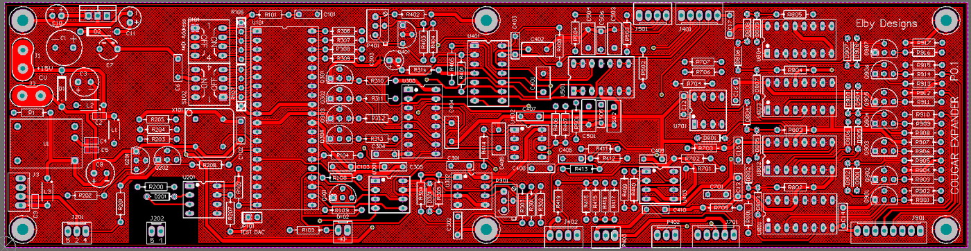
Plan View
|
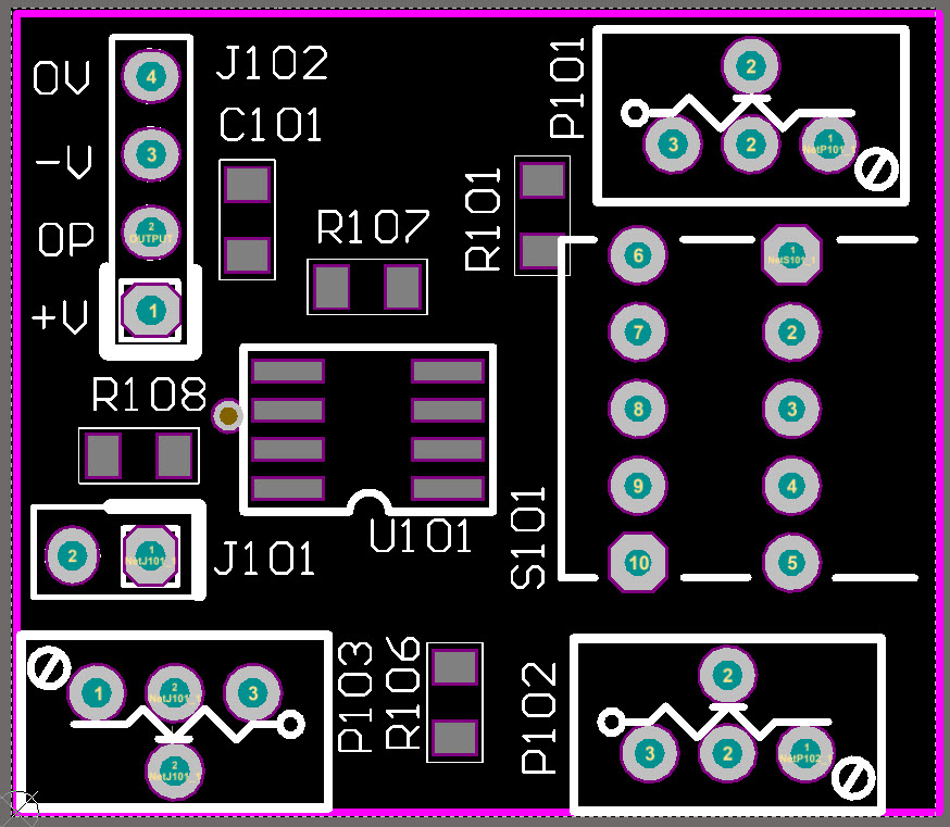
Schematics
|
|
|
|
|
|
|
|
|
|
|
|
|
|
|
|
Constructors should refer to the Component Overlays along with,
the PCB Bill of Materials for the current value of all components, and
the General Construction Notes for general PCB assembly guidelines.
Construction

The ASM-2 Cougar requires the assembly of 2 main PCBs (ASM-2 and Expander) and 2 sub-assemblies (3U Octave). Refer to the relevant build guides for each item:-
- ASM-2
- Expander
- 3U Octave
The 3U Octave and Expander boards involve some surface-mount components (0805 and SO-8 on the Octave PCBs and 0805 on the Expander PCB) but these should be easily handled by most competent constructors.
NOTE:
A front panel design error has resulted in the Pulse Divider section not including a [RESET] socket. We recommend replacing one of the divider outputs, such as [/8] with a [RESET] socket
Housing your ASM-2 Cougar
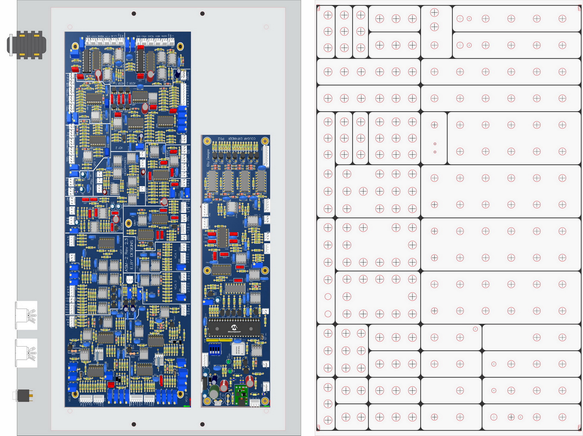
The following notes assume that you are building your ASM-2 Cougar in to either our 84HP Boat, a Studio 500 or a Studio 700.
NB: The Studio 500 and Studio 700 already have a few holes pre-drilled that can be adapted to take the above parts.
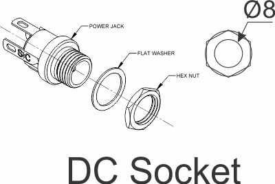
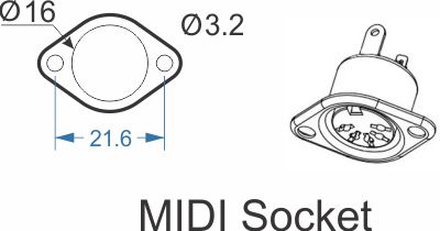
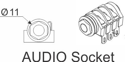
Using the ASM-2 and Expander PCBs as a reference, fit their respective mounting kits to the Synth Base Plate.
-
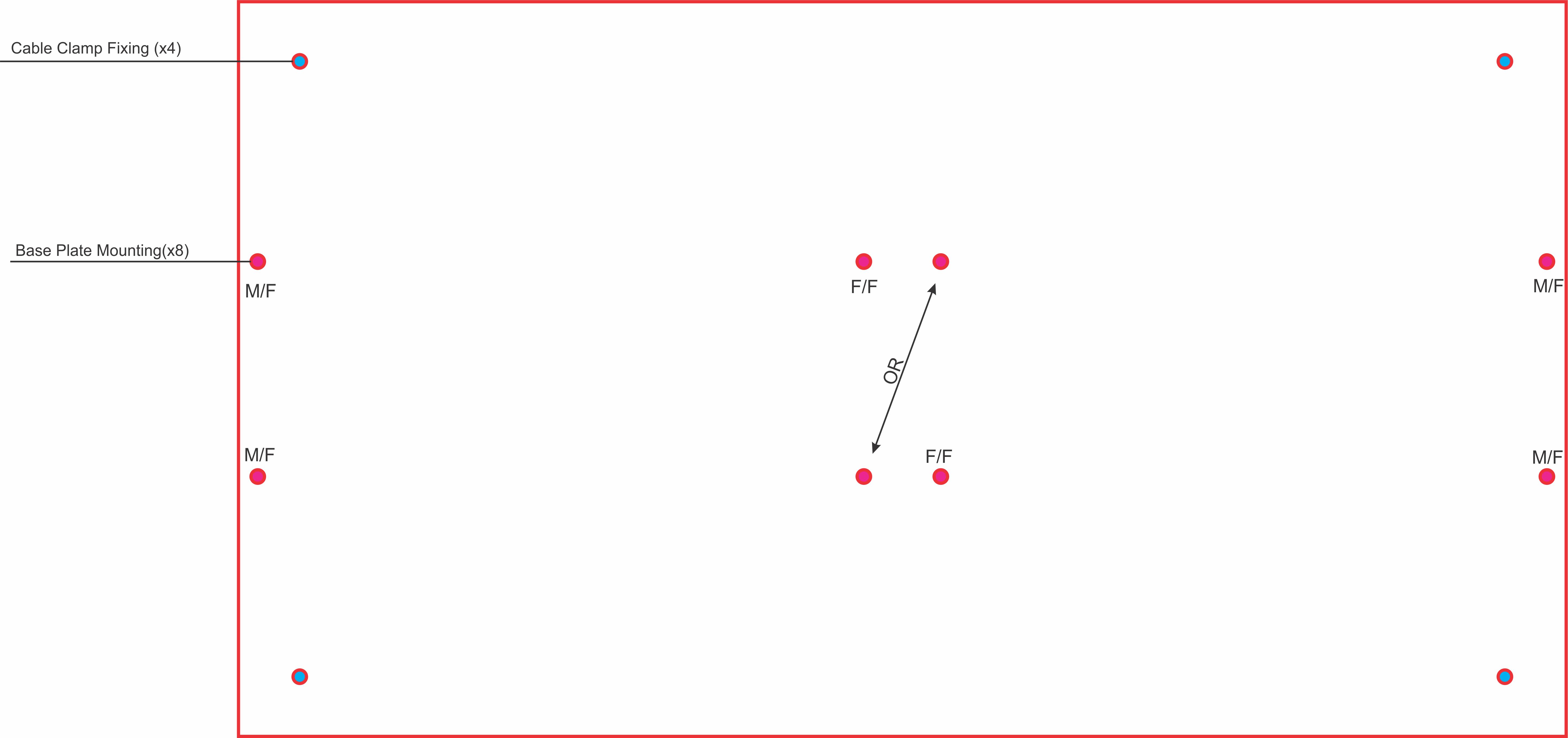
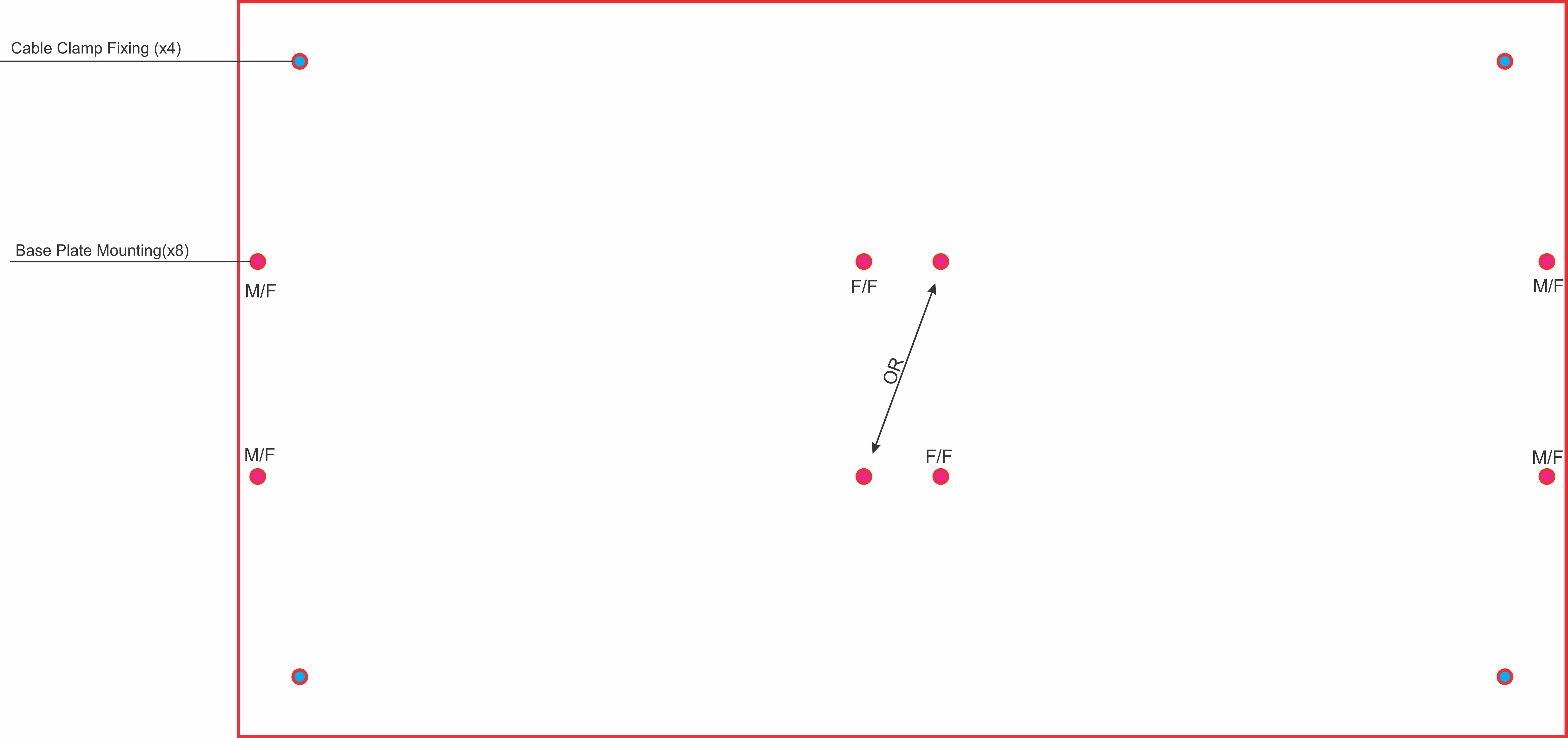
Install the Synth Base Plate using the Synth Base Plate Mounting Kit. This kit includes 4x M4 M/F Spacers and 2x M4 F/F Spacers that support the Base Plate in the base of the Studio Enclosure or boat. The location of the M/F and F/F spacers is shown here. If building your unit in to a boat, you will need to drill mounting holes (4.2mm) and you should use the Synth Plate as a template.