- Assemble the S101 DPDT switch sub-assembly (3D Model)
- Assemble the J4 jack sub-assembly (3D Model)
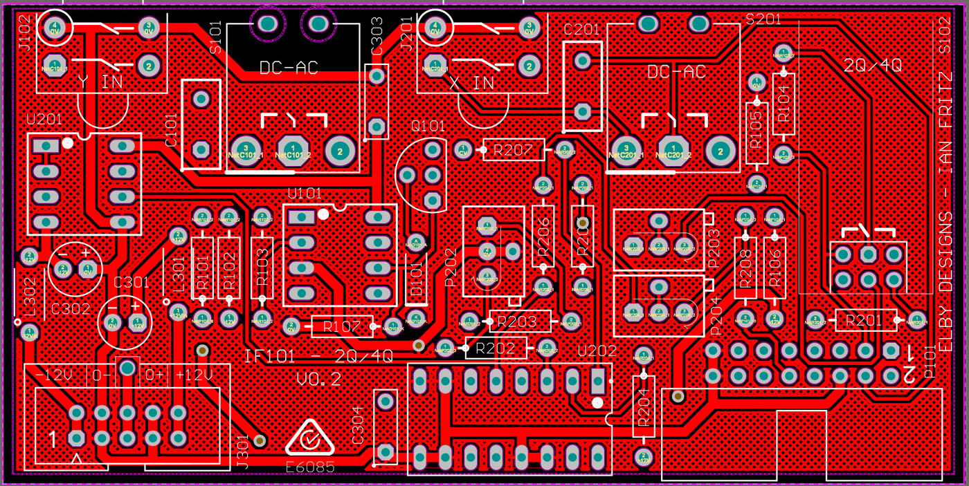
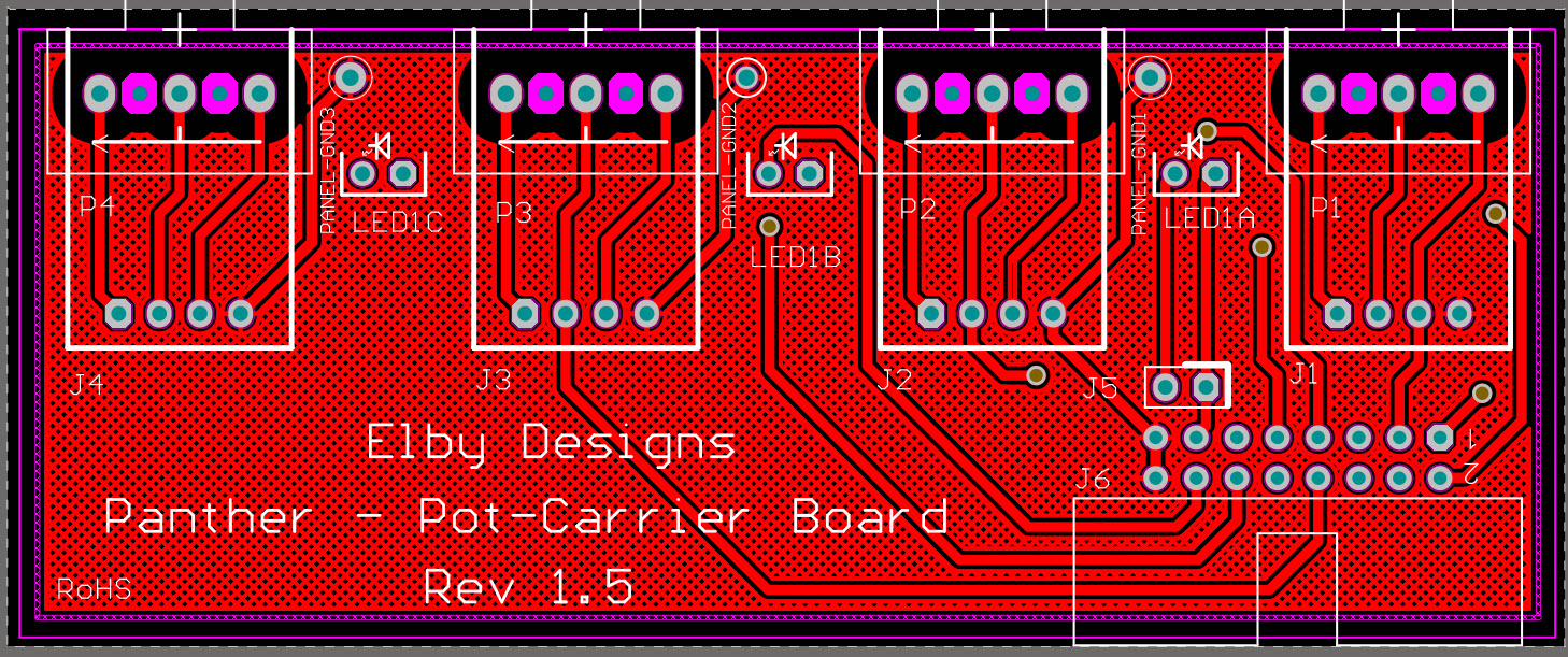
- Fit all components to their respective PCBs except for S101, S102, S201 on the Column 1 PCB and J4 on the Column 2 PCB
- Once installed, remove the spacer bar from the header for S102
- Mount S101, S102 & S201 onto the Column 1 PCB but do not solder
- Offer the assembly up to the Front Panel and secure using the supplied nuts
- Check that the bodies of the switches are parallel to the PCB to ensure the toggle action is vertical and solder in to place
- Mount the Jack sub-assembly onto the Column 2 PCB but do not solder
- Offer the assembly up to the Front Panel and secure using the supplied nuts and washers, and then solder in to place
|
|


