Monitor TP-A4 with an oscilloscope or frequency meter
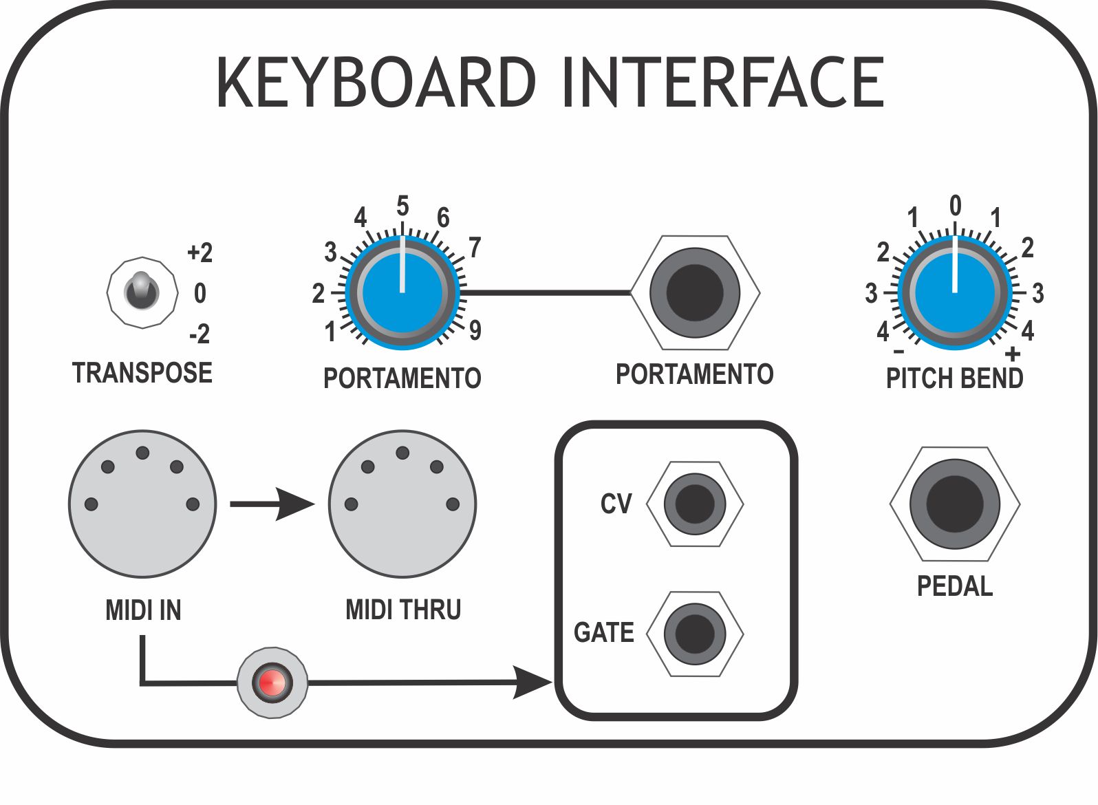
Set [TRANSPOSE] to '+2'
Adjust P1201 for an output of +2.0V
Set [TRANSPOSE] to '-2', output should be -2.0V
The readings should, ideally, be within +/-0.05V of 2.0 at each end. If not, readjust P1201 and repeat measurements until both '+2' and '-2' settings give an 'as near' even swing either side of 0.0V.
TP-A4
CV-OUT
P1203
Set [TRANSPOSE] to '0'
Set [PITCH BEND] full clockwise
Monitor TP-A4
Adjust P1203 for an output of 1.0V
Set [PITCH BEND] fully counter-clockwise, the reading should be -1.0V
The readings should be 1.0V or slightly greater at each end. Adjust P1203 and repeat measurements at both ends until [PITCH BEND] swings past +1.0V and -1.0V at either end.
Operational Checks
Test Point
Procedure
TP-A3
CV-MEMORY
Connect a MIDI Keyboard or suitable controller to [MIDI IN]
Set [TRANSPOSE] to '0'
Set [PITCHBEND] to '0'
Set [PORTAMENTO] fully counter-clockwise
Monitor TP-A3 with a multimeter
Press 'BOTTOM C' on the keyboard, the reading should be 0.0V
Press 'MIDDLE C', the reading should be 2.0V
Press 'TOP C', the reading should be 5.0V
TP-A3
CV-MEMORY
Press a few different keys and confirm that the voltage jumps immediately to a new value.
Confirm that changing the position of [PORTAMENTO] results in each change of key generates a gradual rise/fall in voltage to each new value and that the rise/fall takes longer as [PORTAMENTO] is turned clockwise
TP-A5
GATE
Monitor TP-A5 with an oscilloscope or multimeter
Press and hold any key on the keyboard
Check that the signal swings from +15V to 0V and remains low while the key is held
Release the key and confirm the signal returns to +15V
TP-A6
MEMORY GATE
Monitor TP-A7 with an oscilloscope or multimeter
Press and hold any key on the keyboard
Check that the signal swings from 0V to +15V and remains low while the key is held
Release the key and confirm the signal returns to 0V
TP-A7
GATE OUT
Monitor TP-A7 with an oscilloscope or multimeter
Press and hold any key on the keyboard
Check that the signal swings from 0V to over +10V and remains low while the key is held
Release the key and confirm the signal returns to 0V
TP-A8
TRIGGER OUT
Monitor TP-A8 with an oscilloscope
Press and hold any key on the keyboard
Check that the signal swings from 0V to over +10V and returns to 0V with a pulse-width greater than 200mS