| |
3D Model |
Overlay |
Plan View |
|
|
|
|
Constructors should refer to the Component Overlays along with,
the Bill of Materials for the current value of all components, and
the General Construction Notes for general PCB assembly guidelines.
Construction of the MIDI-Retrofit-16 is pretty straight forward. Attention must be paid, as usual, to the orientation of polarized components and the usual ESD procedures should be in place when handling sensitive components.
Construction should follow these simple steps:-
- Dress the MIDI-Retrofit-16 PCB with all components as required – see Build Options
- Install the board using the four mounting points
- Install all required panel components
- Connect panel components to the board using equipment wiring and the supplied crimp terminals
Build Options
There are, basically, 3 installation options:-
Install MIDI-Retrofit-16 inside the equipment to be controlled
-
Mount MIDI-Retrofit-16 into a small ABS enclosure fitted with a multi-pin connector through which connection is made to the equipment to be controlled
-
Mount MIDI-Retrofit-16 inside a large enclosure complete with output jacks and panel mounted status indicators.
Option 1 - Internally mount in equipment to be controlled
-
The MIDI-Retrofit-16 should have a minimum of 5mm clearance in all directions and be securely mounted to prevent movement. Power is derived from the equipments supply or an additional power source can be added.
-
As a minimum you will need to mount the MIDI IN socket in a convenient location.
-
The MIDI-Retrofit-16 will, most likely, only need to be programmed once so there is no need for a panel mounted LEARN switch. when needed, the unit can be opened and the 2 pins on the LEARN connector momentarily shorted to activate the LEARN mode.
-
Although not essential, it is desirable to have the LEDs installed. This will greatly assist with the LEARN process and is a useful means of confirming operation of the unit. If the LEDs cannot be panel mounted then they can be direct wired in to the connector housing and mounted directly on to the LED connectors.
|
Option 2 - Externally mounted
The MIDI-Retrofit-16 footprint has been designed to fit in to a 140mmx 110mm x 35mm ABS enclosure commonly found in electronic/hobby stores.
-
There is room at the front of the assembly to fit a multi-pin D-Sub Type connector (we use a 37-pin model). This connector is used to feed the TRIGGER outputs, LED status indicator outputs, power rails and the LEARN switch.
-
A slightly larger enclosure would allow the LEDs to be mounted on the enclosure which will aid with running the LEARN mode and provide visual indication of the operation of the unit.
- If the equipment to be controlled does not have a suitable power source for the MIDI-Retrofit-16 then a DC power connector can be mounted on the enclosure and a standard 12V-15VDC power supply used to power the unit.
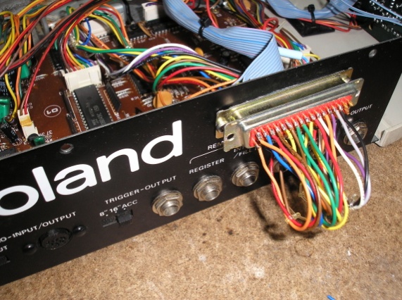
Example of an 'external connector'.
Here it is shown with a loop-back plug fitted to restore normal operation of the equipment.
|
|
Option 3 - Stand-alone Unit
-
A suitably sized enclosure can be used to house the MIDI-Retrofit-16. Jacks would be fitted to allow individual instruments to be plugged in to the TRIGGER outputs. Typically these are 1/4" or 1/8" jacks.
-
Panel mounted LEDs would be fitted along with the LEARN switch.
-
An external power unit (12V-15VDC) would be used to power the unit
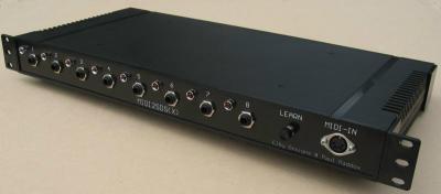
Example of a stand-alone unit.
Here it is ,ounted into a 1U 19"Rack (standard MIDI2SDS(X) shown) |
|


