| |
3D Model |
Overlay |
Plan View |
Column 1 PCB |
|
|
|
Column 2 PCB |
|
|
|
Column 3 PCB |
|
|
|
Constructors should refer to the Bill of Materials 3.5mm 4mm for the current value of all components,
and
the General Construction Notes for general PCB assembly guidelines.
Addendum
- Mount R405 in the right pads of R405 & R407
- Mount R407 in the left pads of R405 & R407
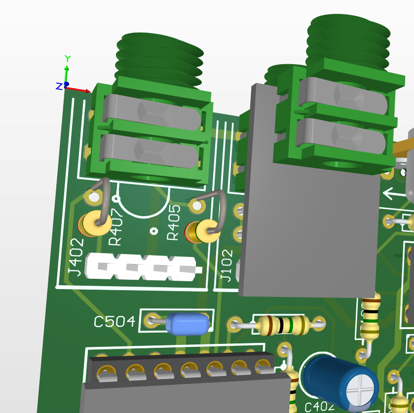
The image shows them mounted vertically to better show their positions on the PCB, but they should be folded over towards each other ensuring that the legs do not contact each other or any other part of the circuit and then locked into position by solder.
After fitting J502 on the Column 3 PCB you need to add 2 short wire links (we suggest forming the appropriate legs of R204 and R304 under when installing them and soldering them to the respective pins on J502) as shown on the overlay :-
- 1 link on the underside from J502_1 to the bottom leg of R204, and
- 1 link on the underside from J502_3 to the right leg of R304.
The Column 3 PCB has been factory modified for this modification.


