|
3D Model
|
Overlay
|
Plan View
|
|
|
|
|
|
|
|
|
|
|
|
|
|
|
|
|
|
|
|
|
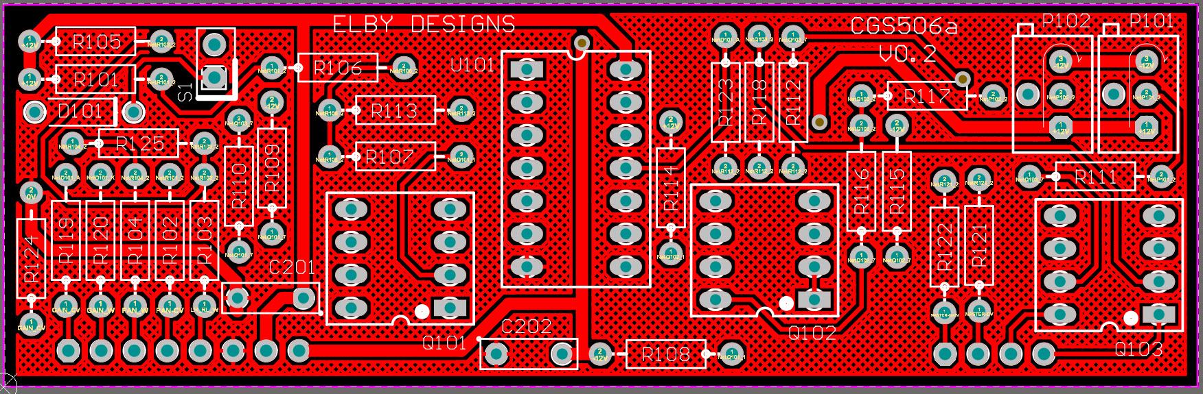
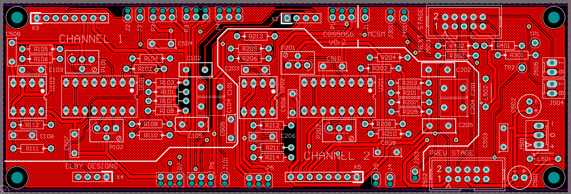
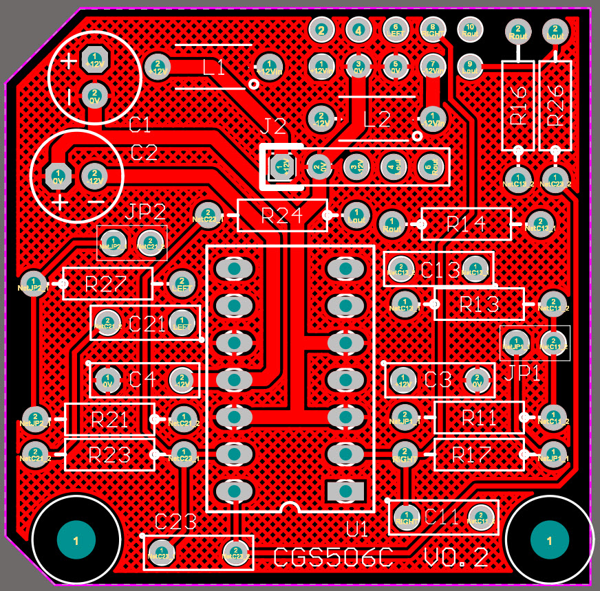
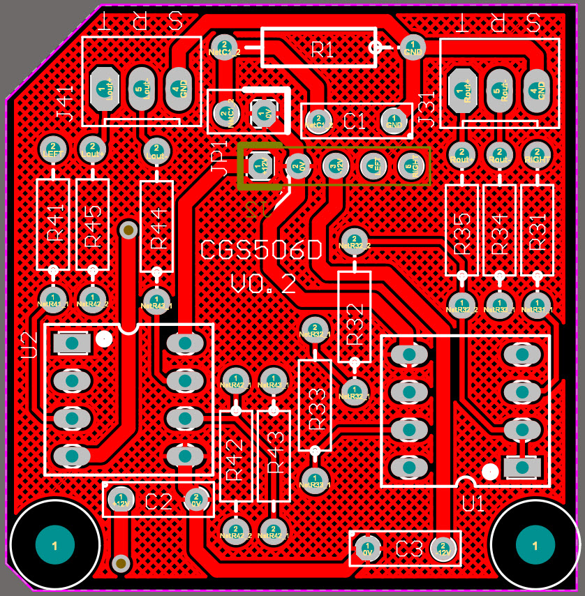
Constructors should refer to the Component Overlays along
with,
the Bill of
Materials for the current value of
all components, and
the General
Construction Notes for general PCB
assembly guidelines.
If building the CGS506 as a Stereo
Mini Mixer then J1, P4 & P7 are not used
and should be replaced with wire links as
shown in the wiring diagram.
Two jumpers on the CGS506c PCB allow
the user to select Consumer Line Level
(-10dBV) or Professional Line Level (+4dBU).
This setting affects both the unbalanced and
balanced outputs. Leave the jumpers open for
Professional Line Level or fit them both for
Consumer Line Level. These are normally
set-and-forget so simple wire links can be
used in place of jumpers.
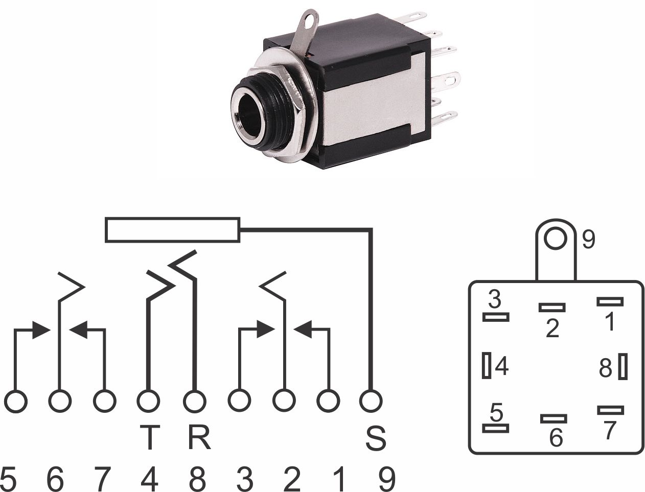
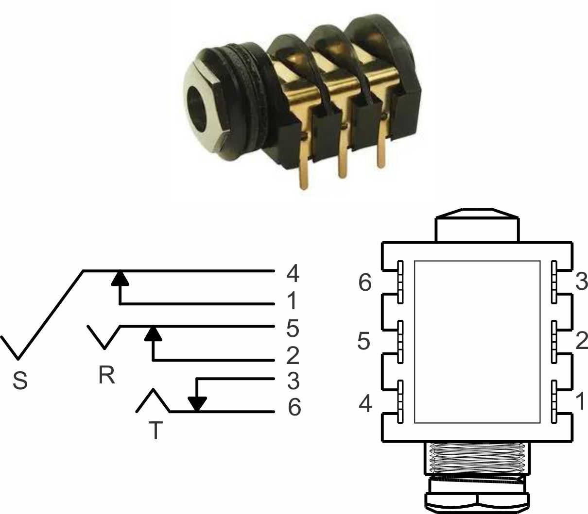
There are 2 types of 1/4" jack
sockets supplied in our kits and their pin-out
details are shown here:-


