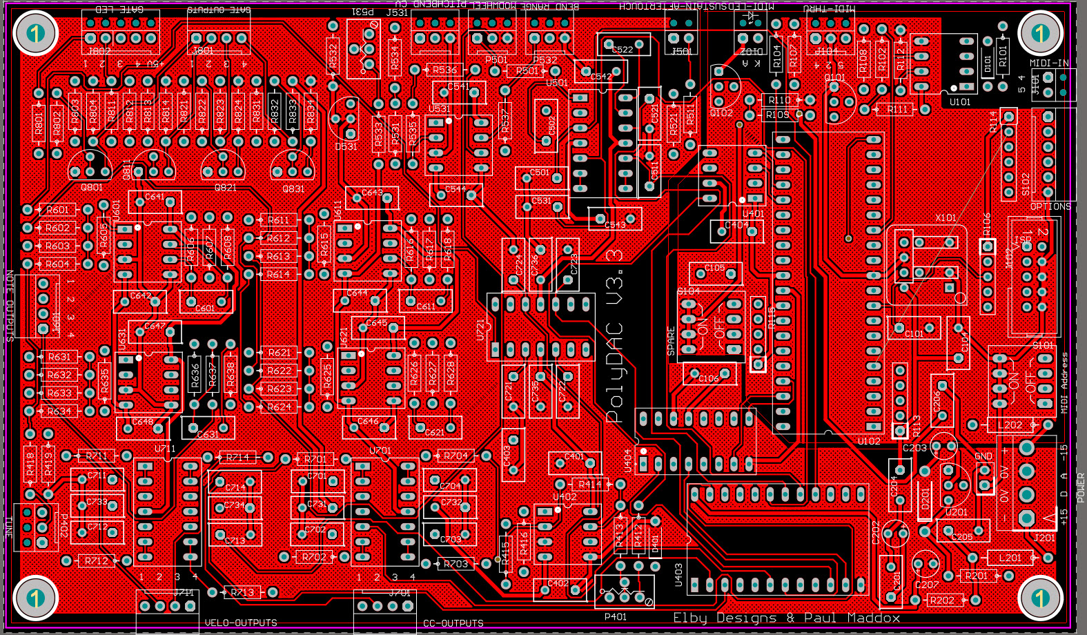
The current release of the PCB (V3.3) requires a JST connector (supplied with the PCB) for the power as the PCB holes are slightly undersized for the more common Molex part. Two PCB errors require a wire links be fitted as follows:-
|
Email: elby-designs@bigpond.com
© Copyright 2000. All rights reserved. Revised: May 14, 2024


© Copyright 2000. All rights reserved. Revised: May 14, 2024