|
3D Model
|
Overlay
|
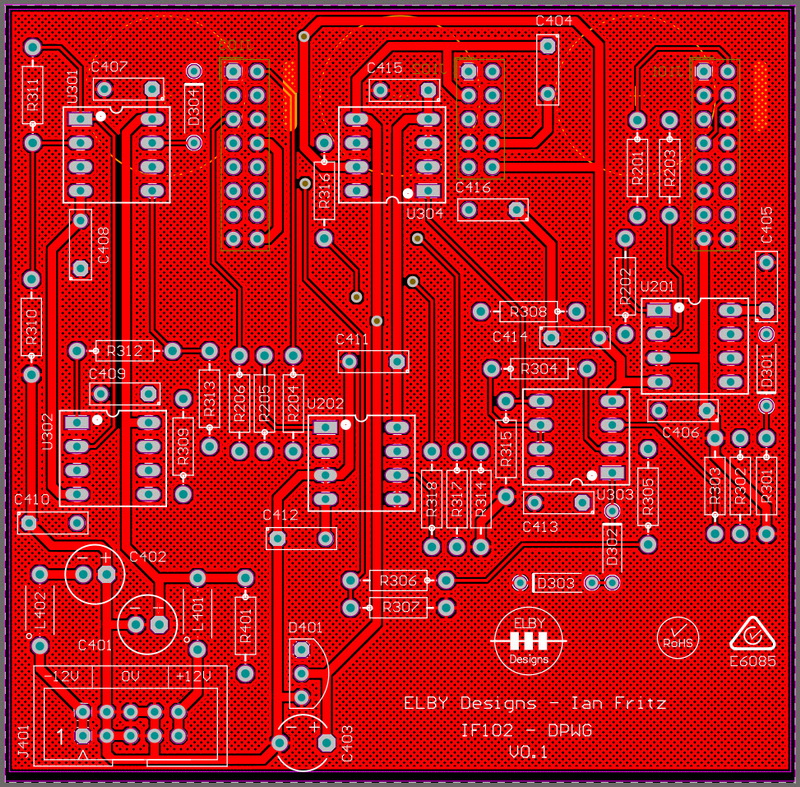
Plan View
|
|
|
|
|
|
|
|
|
|
|
|
|
|
|
|
Constructors should refer to the 3.5mm 4mm Bill Of Materials for the current value of
all components, and
the General
Construction Notes for general PCB
assembly guidelines.
- Assemble
the 5x Jack Carrier Board assemblies (3D
Model)
- Assemble
the 1x Switch Carrier Board assemblies (3D
Model)
- Fit
all components to the boards following
normal assembly guidelines except for all
the jack sub-assemblies and the trimpot.
Select R306 based on the desired nominal
output voltage - 5Vpp for
EuroSynth/EuroSerge or 10Vpp for EuroRack
- Mount
the jack sub-assemblies to the Column 1
board but do not solder
- Offer
the assembly up to the front panel and
secure the using the supplied nuts and
washers
- Solder
the jack sub-assemblies in to place
- Remove the Column 1 assembly
- Mount
the jack and switch sub-assemblies to the
Column 2 PCB but do not solder
- Offer
the assembly up to the front panel and
secure the using the supplied nuts and
washers
- Solder
the jack sub-assemblies in to place
- Guide
the trimpot in to position
- Solder
in to place ensuring that the adjust screw
is central to the panel hole. If you have a
trimtool then use it to help align position the
adjust screw
- Mount
the jack sub-assemblies to the Column 3
board but do not solder
- Offer
the assembly up to the front panel and
secure the using the supplied nuts and
washers
- Solder
the jack sub-assemblies in to place
- Reinstall the Column 1 assembly
- Mount
the backboard ensuring correct alignment of
the IDC connectors.


