|
3D Model |
Overlay |
Plan View |
|
|
|
|
|
|
|
|
|
|
|
|
PCB - Column 12 |
|
|
|
|
|
|
|
Constructors should refer to the Component Overlays along with
the 3.5mm 4mm Build Guides for the current value of all components, and
the General Construction Notes for general PCB assembly guidelines.
Front Panel Preparation
- Fit 8x LED mounting lenses in the Column 1 to Column 8 positions
- Fit an LED mounting lens in the Column 12 position
- If using one of our racking solutions, cut off 2 of the mounting legs on one side of the remaining lens mount and insert in to the [MIDI IN] position with the cut section nearest the edge of the panel, otherwise mount the lens as normal
- Fit 2x MIDI sockets
- Prepare the LED for Column 11 as per the General Construction Notes
Column 1 to Column 8 PCB Assembly
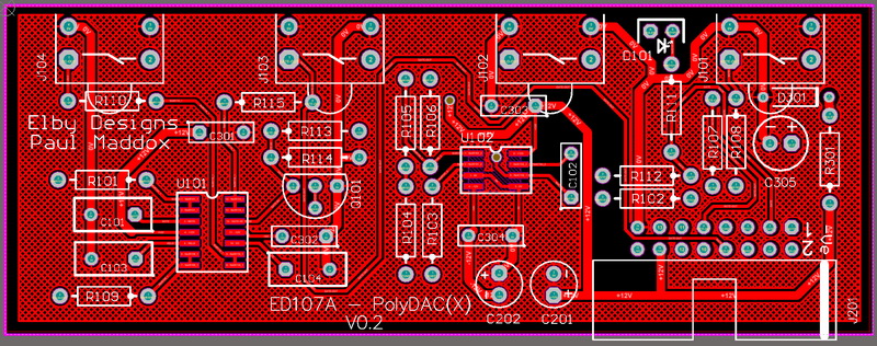
- Populate all the ED107A PCBs (Coulmn 1 - Column 8) except for their LEDs
- Offer the Column 1 assembly up to the panel and secure using the supplied nuts
- Form the LED and fit onto the PCB, positiong the LED bulb firmly into its mating lens mount - solder into place
- Repeat for the remaining 7x ED107A assemblies.
Column 9 PCB Assembly
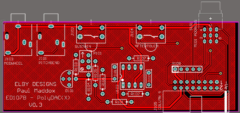
- Fully populate the PCB
- Offer the assembly up to the front panel ensuring that the [MIDI ADDRESS] sits squarely in to its panel cutoutand secure using the supplied nuts and secure using the supplied nuts for the [AFTERTOUCH] & [SUSTAIN].
- The [PITCHBEND] and [MODWHEEL] will not accept fixing nuts
Column 10 PCB Assembly
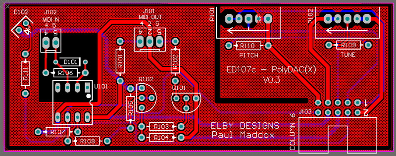
- Populate the PCB except for the MIDI socket connectors (Do not fit MTA sockets if supplying your own parts)
- Cut the wires in to 5 equal lengths (2x Yellow, 2x Green and 1x Red)
- Trim approximately 3mm off the end of each piece of wire and lightly twist
- Solder the wires into the PCB. Yellow to the pads marked '2', Green to the pad marked '5' and Red to the pad marked '2' on the overlay
- Offer the PCB up to the front panel and secure using the supplied nuts and washers
- Solder the wires into their respecitve pins on the sockets
Column 11 PCB Assembly
- Populate the PCB including the prepared LED
- Offer the assembly up to the front panel and secure using the supplied nuts and form the LED wires so that the LED body sits squarely in its lens mount
Column 12 PCB Assembly
- Populate the PCB except for the LED
- Mount the LED but do not solder, offer the assembly up to the front panel and secure using the supplied nuts
- Position the LED so that the LED body sits squarely in its lens mount and solder into place
Main PCB Assembly
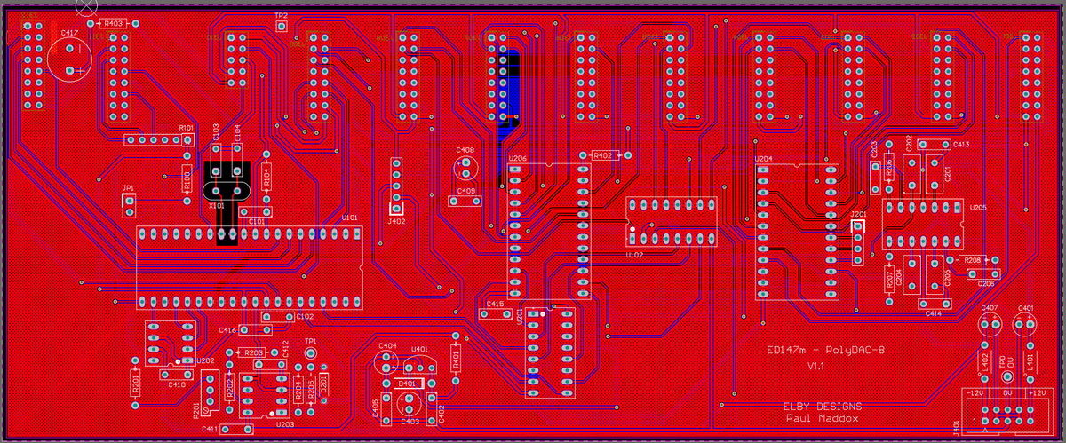
- Fully populate the PCB
- Offer the Main PCB up to the Column PCBs ensuring that all IDC receptacles properly align within their respective IDC sockets