| |
|
3D Model |
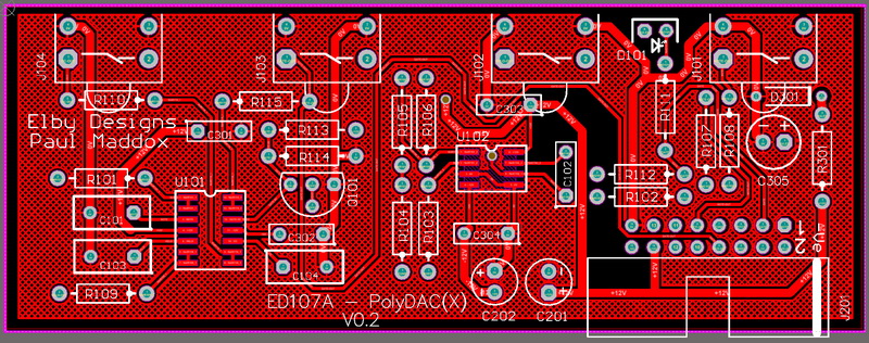
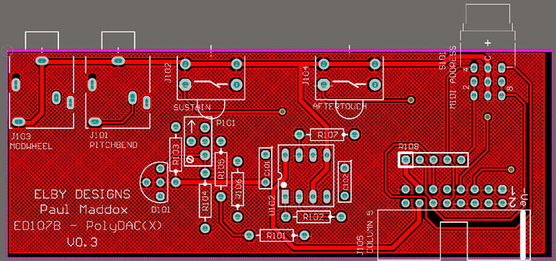
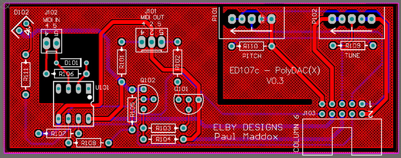
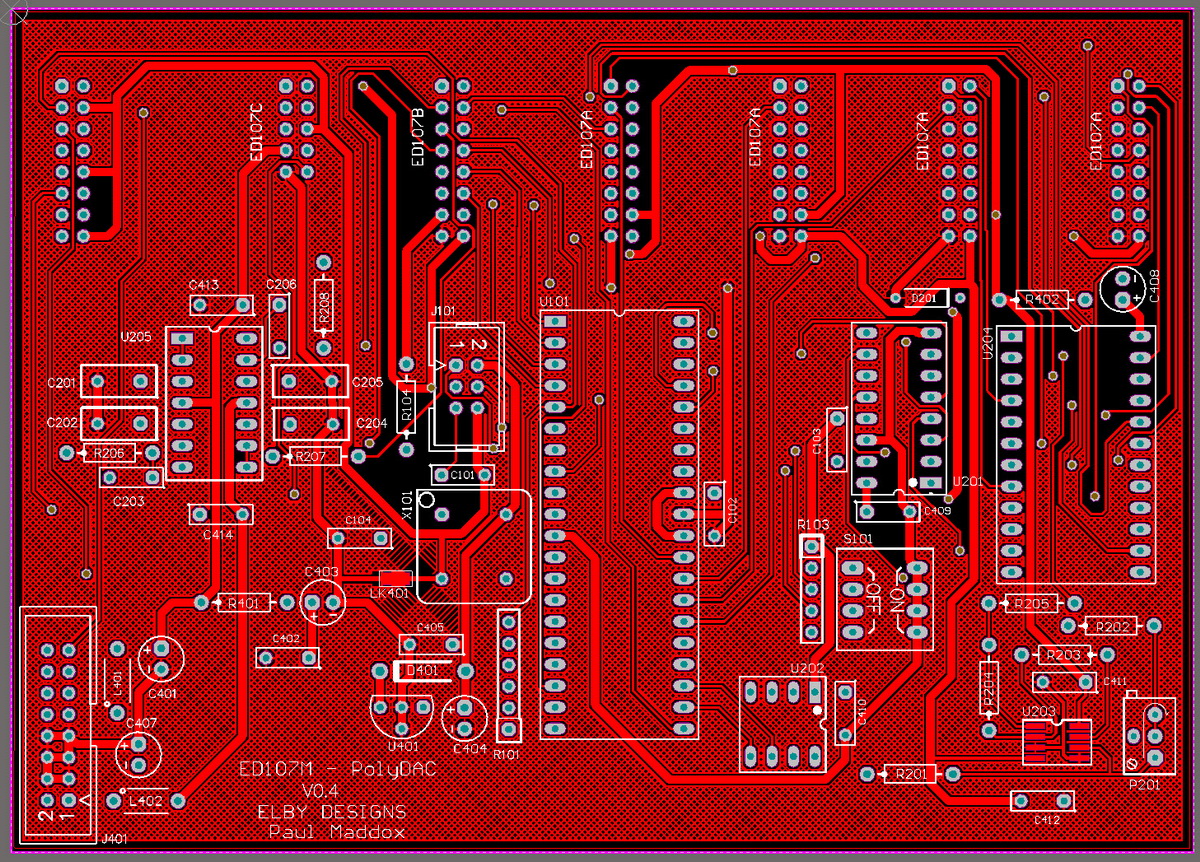
Overlay |
Plan View |
|
|
|
|
|
|
|
|
|
|
|
|
PCB - Column 7 |
|
|
|
|
|
|
|
Constructors should refer to the Component Overlays along with
the Bill of Materials for the current value of all components, and
the General Construction Notes for general PCB assembly guidelines.
- Populate all PCBs as per their respective section in the BOM.
- For ED107C, trim approximately 3mm off the end of each piece of wire and lightly twist.
- Solder the wires into the PCB for J101 and J103,
- Trim the wires to a similar length and then strip and twist 1mm-2mm off the free ends
- Mount the 2x MIDI sockets onto the front panel
- Fit the lens mounts under each of the [NOTE] sockets
- If using one of our racking solutions, cut off 2 of the mounting legs on one side of the remaining lens mount and insert in to the [MIDI IN] position with the cut section nearest the edge of the panel, otherwise mount the lens as normal
- Offer up the ED107c assembly and secure using the nuts supplied
- Solder the wires onto their respective pins on the MIDI sockets
- Offer up the ED107b to the front panel ensuring that the [MIDI ADDRESS] sits squarely in to its panel cutout
- Secure using the supplied nuts for the [AFTERTOUCH] & [SUSTAIN] sockets (the [PITCHBEND] and [MODWHEEL])
- Finish assembly by installing the remaining panels, check that the LEDs on the ED107a align properly into their len smounts.
|
|
|


