| |
3D Model |
Overlay |
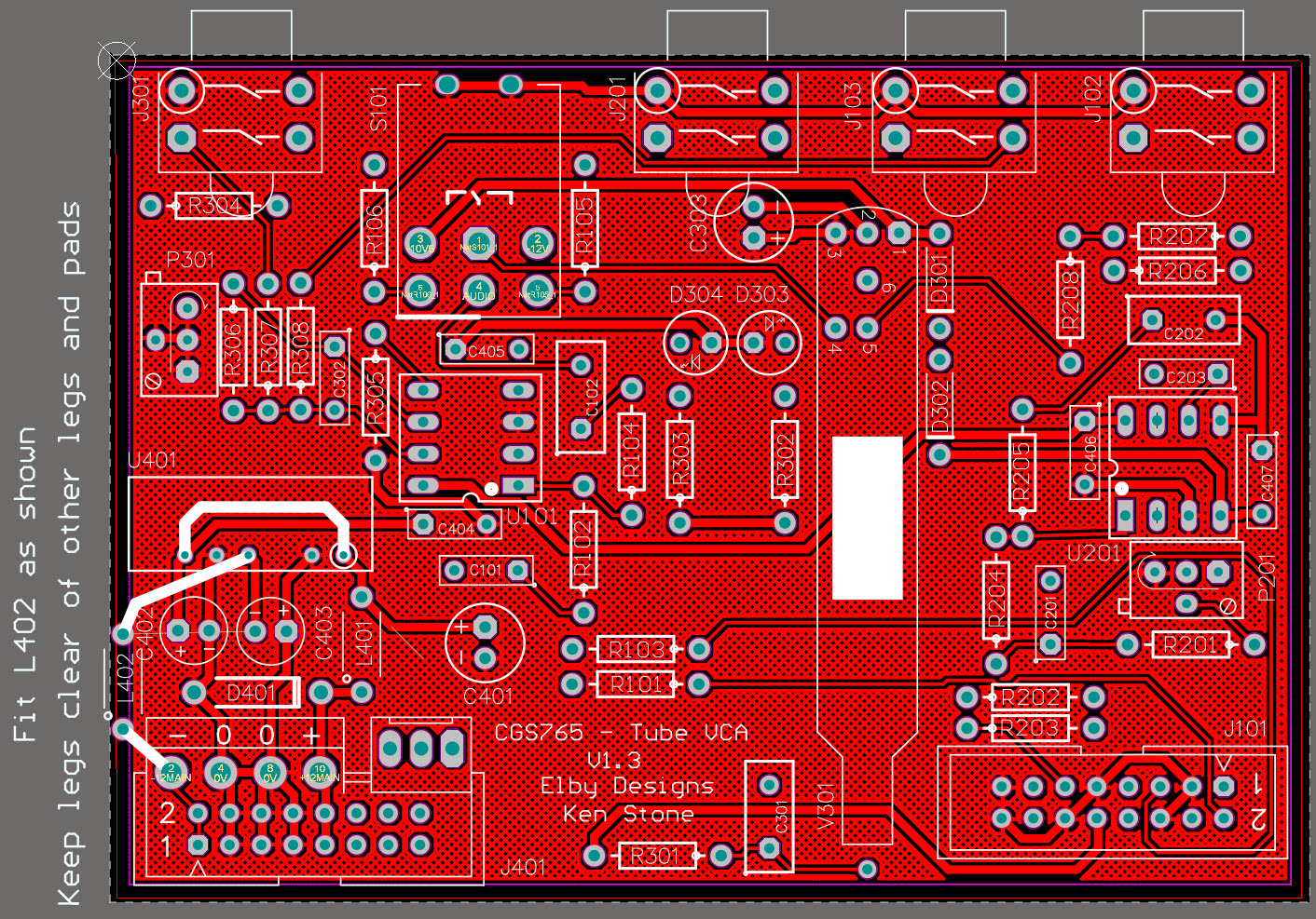
Plan View |
|
|
|
|
Constructors should refer to the Component Overlays along with,
the Bill of Materials for the current value of all components, and
the General Construction Notes for general PCB assembly guidelines.
- Start assembly with the main board fitting all components except
the valve and switch, D401 and U401
- See Addendum for D401/U401
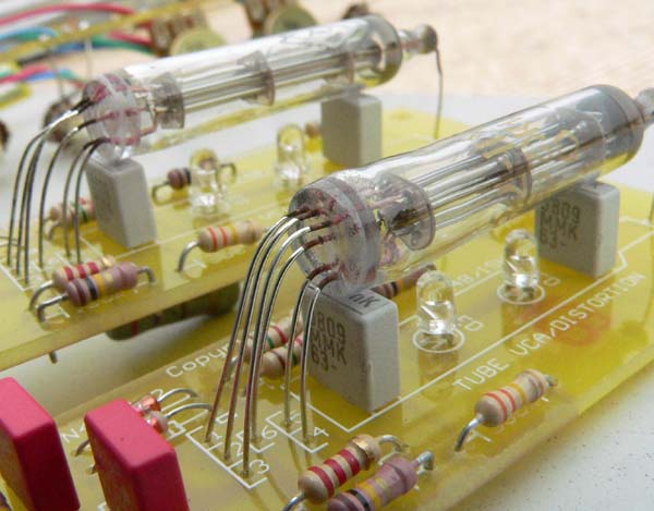
- Refer to picture below (this is a different version of the PCB).
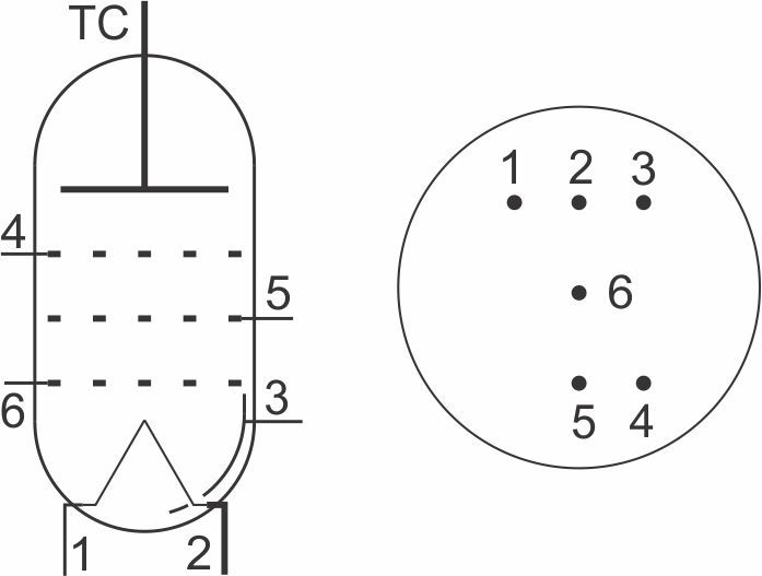
- Carefully straighten the legs out on the valve
- Holding the valve upright, align the legs of the valve with the pads on the PCB
- Lower the valve until its end is about 3cm above the board
- Start folding the tube over until it is parallel with the board using a
pair of narrow-nose pliers to carefully form the leads as you go
- The tube should finish up about 1cm above the board
- Place the piece of supplied foam on to the marked area on the
PCB and press the tube gently down against the PCB/foam with a little
firm pressure and solder the leads in to place
- Place the switch on to the PCB and offer up to the front panel
securing it using a couple of jack nuts
- Fit and tighten a nut to the switch ensuring that the switch toggle
action is vertical. When happy, solder in to place
- Assemble the Panther Support board and attach to the module
- Fit the Panther IDC cable to connect the 2 boards
- Finish assembly by adding remaining nuts and knobs.
ADDENDUM
The original CGS765 build used a dual-rail
step-up regulator to generate +/-15VDC from
the +12V rail.
We have subsequently found that reverting back to the systems +/-12V rails provides for more stable operation and so in the current build the
regulator has been bypassed. This requires
the addition of a wire link and a ferrite bead
as shown in the picture below.
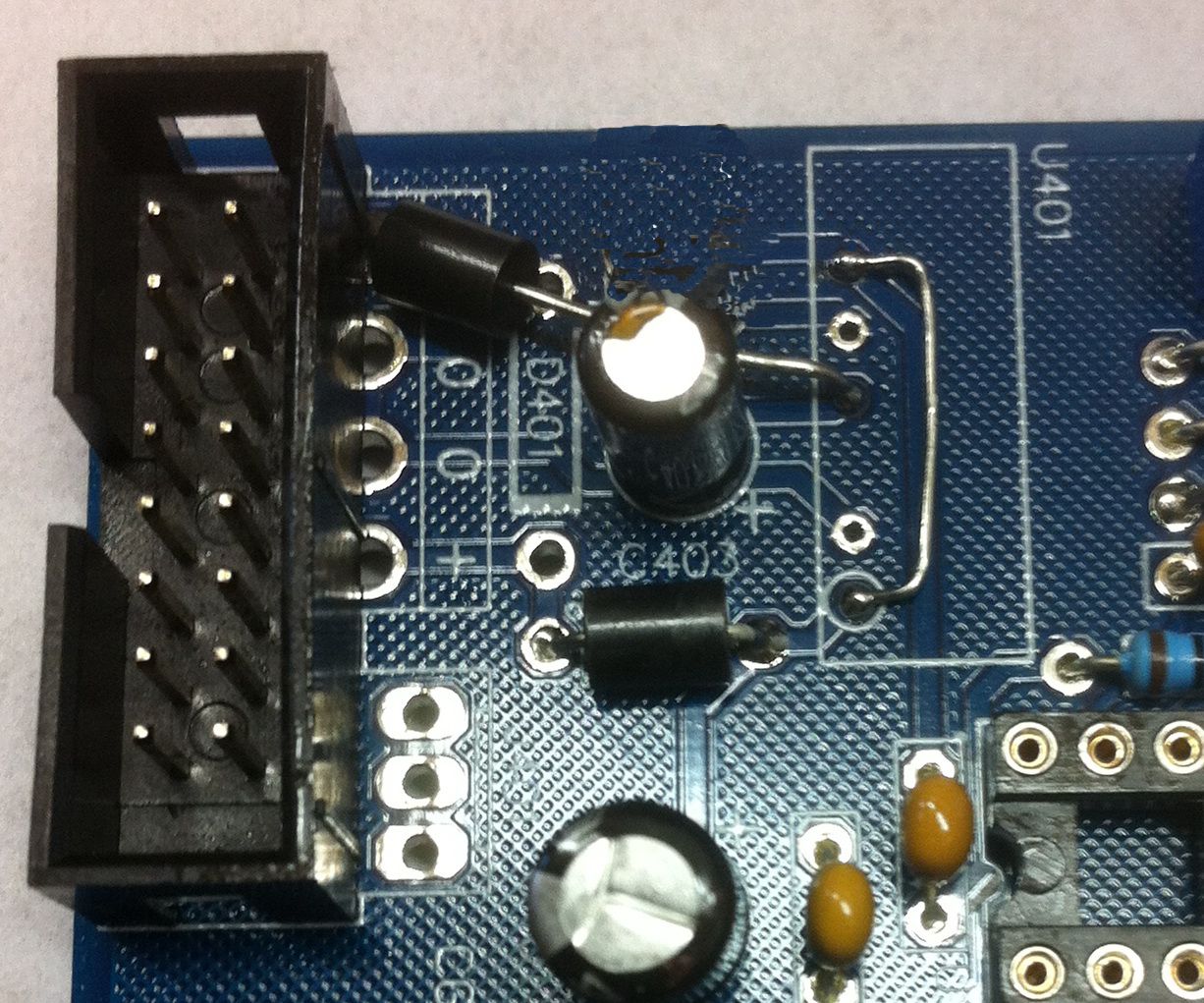
Ensure that when fitting the 2 parts that they
do not short against any exposed component parts.


