|
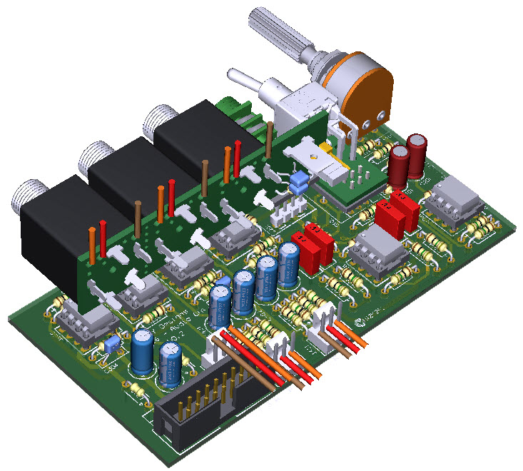
3D Model |
Overlay |
Plan View |
|
|
|
|
|
|
|
|
Constructors should refer to the Bill of Materials for the current value of all components,
and
the General Construction Notes for general PCB assembly guidelines.
- Assemble the Jack Carrier (J101) sub-assembly (3D Model)
- Assemble the Switch Carrier (S201) sub-assembly (3D Model)
- Fit all components to the main board following normal assembly guidelines
except the J101 and S201 sub-assemblies
- Mount the 2 sub-assemblies and offer up to the front panel securing using the
supplied nuts
- Check that the switch action is properly aligned and then solder the sub-assemblies into position
- Solder wires to the indicated points on the Support Board, using the anchor points to hold the wires secure - see Wiring Guide
- Fit the remaining components excluding the 3x jacks
- Loosely mount the 3x jacks on to the front panel
- Check that the slanted corner of each jack is furthest from the nearest edge of
the panel and that the jack bush is properly located in the panel, and then finger-
tighten the nut
- Offer up the Support Board and solder in to place
- Adjust the lengths of the 3 wires for J1 so that they are all the same and then strip approximately 3mm off
each wire and attach the crimps
- Repeat for J2 and J3
- Fit the crimped wires in to the 3x MTA housings and connect to their
respective headers on the main board as per the updated Wiring Guide
Balanced Output Screen Connection
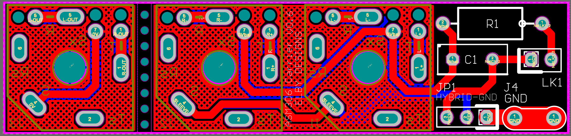
The balanced outputs should have their 'screen' connection properly terminated. The following options are suggested:-
- Set the jumper JP1 to the 'GND' position and connect a wire from J4 to a suitable CHASSIS GROUND point in your system, OR
- Set the jumper JP1 to the 'HYBRID' position.
Option 1 is the best solution but in many systems is the least practical to achieve as most systems use a floating power supply brick (Class II) and a true GND/EARTH connection is not supplied.
Addendum
Currently the crossfeed circuit also feeds into the balanced outputs. It may be preferred
that this function not be available at the balanced outputs. If so, lift R401 and R411 and
wire the free ends to the points on the crossfeed switch as shown on the ASM306 overlay.