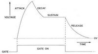
ADSR ENVELOPE
| Test Point |
|
Procedure |
TP-C6 |
|
- Monitor TP-C6 with an oscilloscope
- Set [ATTACK], [DECAY] and [RELASE] fully counter-clockwise and [SUSTAIN] fully clockwise
- Press and hold 'MIDDLE C' for 2 seconds and then release and wait for 2 seconds
- Confirm that the signal quickly rises from 0V to over +8V and returns to 0V when the key is release
- Set [SUSTAIN] to '5'
- Press and hold 'MIDDLE C' for 2 seconds and then release and wait for 2 seconds
- Confirm that the signal quickly rises from 0V to over +8V and then quickly drops to about +4V where it should remain until the key is released
- Confirm that adjusting [ATTACK], [DECAY] & [RELEASE] varies the rise and fall times of their respective slopes
- and that adjusting [SUSTAIN] varies the level at which the 'held on' level rests
|
TP-B10 |
|
- Monitor TP-B10 with an oscilloscope
- Set [ATTACK], [DECAY] & [RELEASE] to '2'
- Set [SUSTAIN] to '5'
- Press and hold 'MIDDLE C' for 2 seconds and then release and wait for 2 seconds
- Confirm that the observed signal is inverted and swings from 0V to approximately -4V
|
AR ENVELOPE
| Test Point |
|
Procedure |
TP-C5 |
|
- Monitor TP-C5 with an oscilloscope
- Set [ATTACK] and [RELEASE] fully counter-clockwise
- Press and hold 'MIDDLE C' for 2 seconds and then release
- Confirm that the signals rises quickly from 0V to +10V and returns quickly to 0V when the key is released
- Confirm that adjusting [ATTACK] & [RELEASE] varies the rise and fall times of their respective slopes
|
LFO
| Test Point |
|
Procedure |
TP-B7 |
|
- Monitor TP-B7 with an oscilloscope
- Confirm that adjusting [FREQUENCY] varies the rate of the LFO TRIANGLE waveform from a period of around 9 seconds per cycle to over 20Hz
- Confirm that the waveform swings approximately from -4V to +4V
|
TP-B8 |
|
- Monitor TP-B8 with an oscilloscope
- Confirm that signal is a squarewave with an approximate 50% duty-cycle
- Confirm that the signals swings from 0V to over +12V
|
NOISE
| Test Point |
|
Procedure |
TP-A9 |
 |
- Monitor TP-A9 with an oscilloscope and confirm that you see WHITE Noise with an amplitude of around 10Vp-p centered around 0V
|
TP-A10 |
 |
- Monitor TP-A10 with an oscilloscope and confirm that you see PINK Noise with an amplitude of around 7Vp-p centered around 0V
|
|
|