|
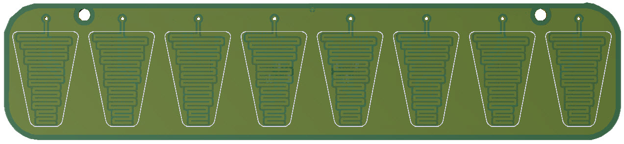
3D Model |
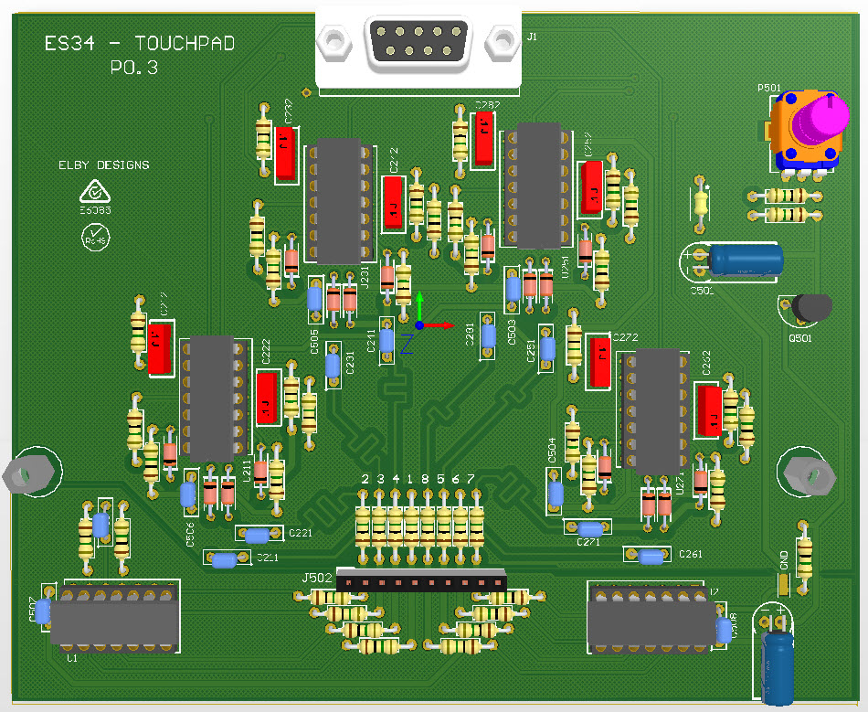
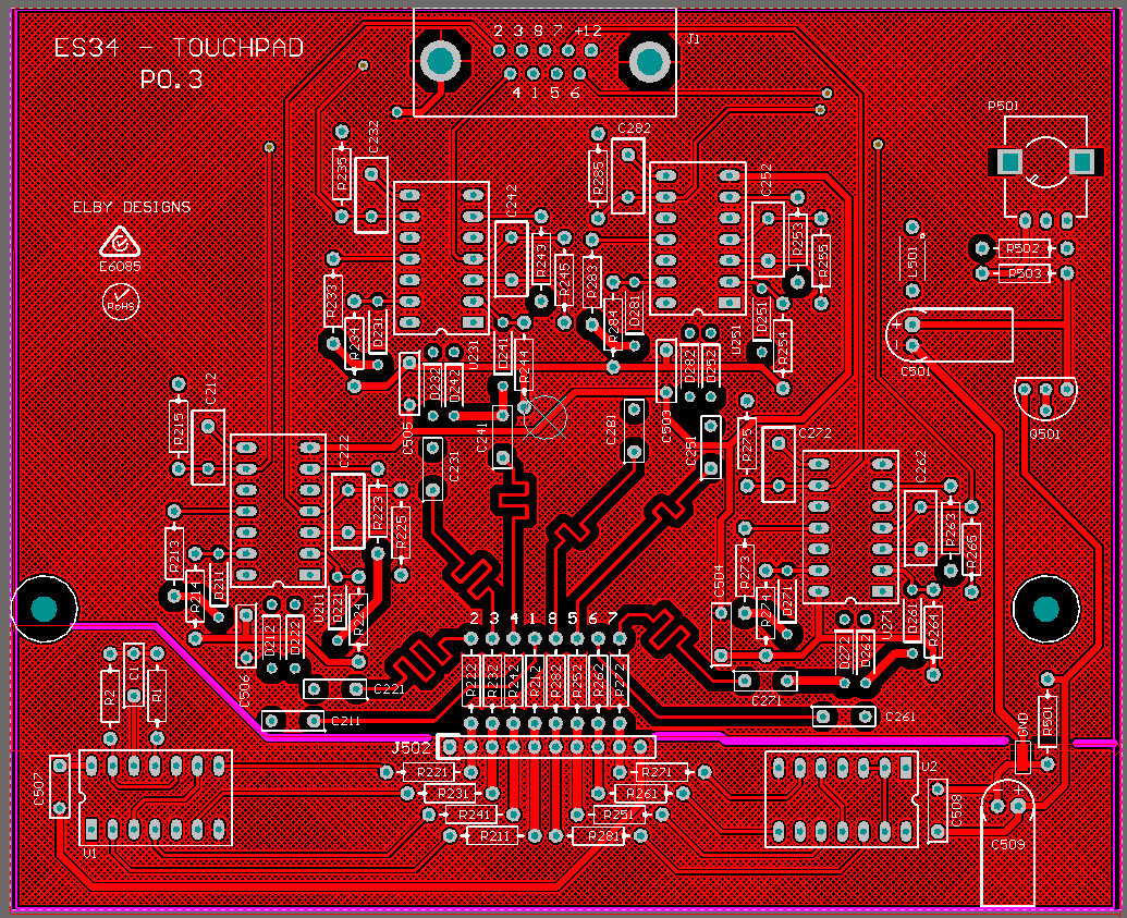
Overlay |
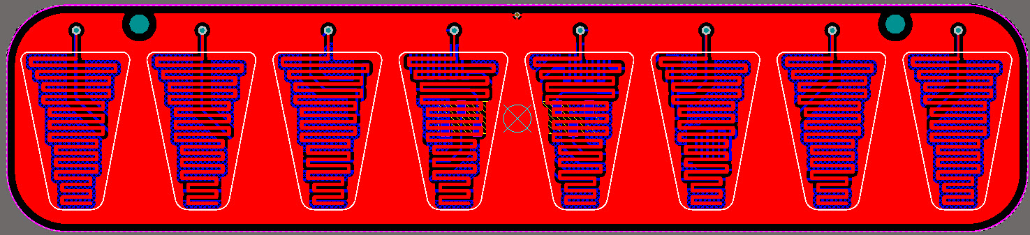
Plan View |
|
|
|
|
|
|
|
|
Constructors should refer to the Component
Overlays along with,
the Bill Of Materials or the current value of all components, and
the General
Construction Notes for general PCB
assembly guidelines.
- Mount
the connector J101 onto the TouchBoard being careful
not to mark the front face of the PCB
- Fit
all components to the ES34 board except for the DB9
connector (J1). NB: If C501 and/or C509 are taller
than 10mm then they should be laid flat against the
PCB
- Mount
1x M3 x 10mm standoff to the Main PCB at one of the
J1 fixing points using an M3 x 6mm bolt. At the
other fixing point include an M3 shakeproof washer
and M3 tag (see
drawing)
- Mount
the RS232 connector and solder into place ensuring
that the connector is sitting hard against the
spacers (temporarily secure with the RS232 Locknuts
if desired)
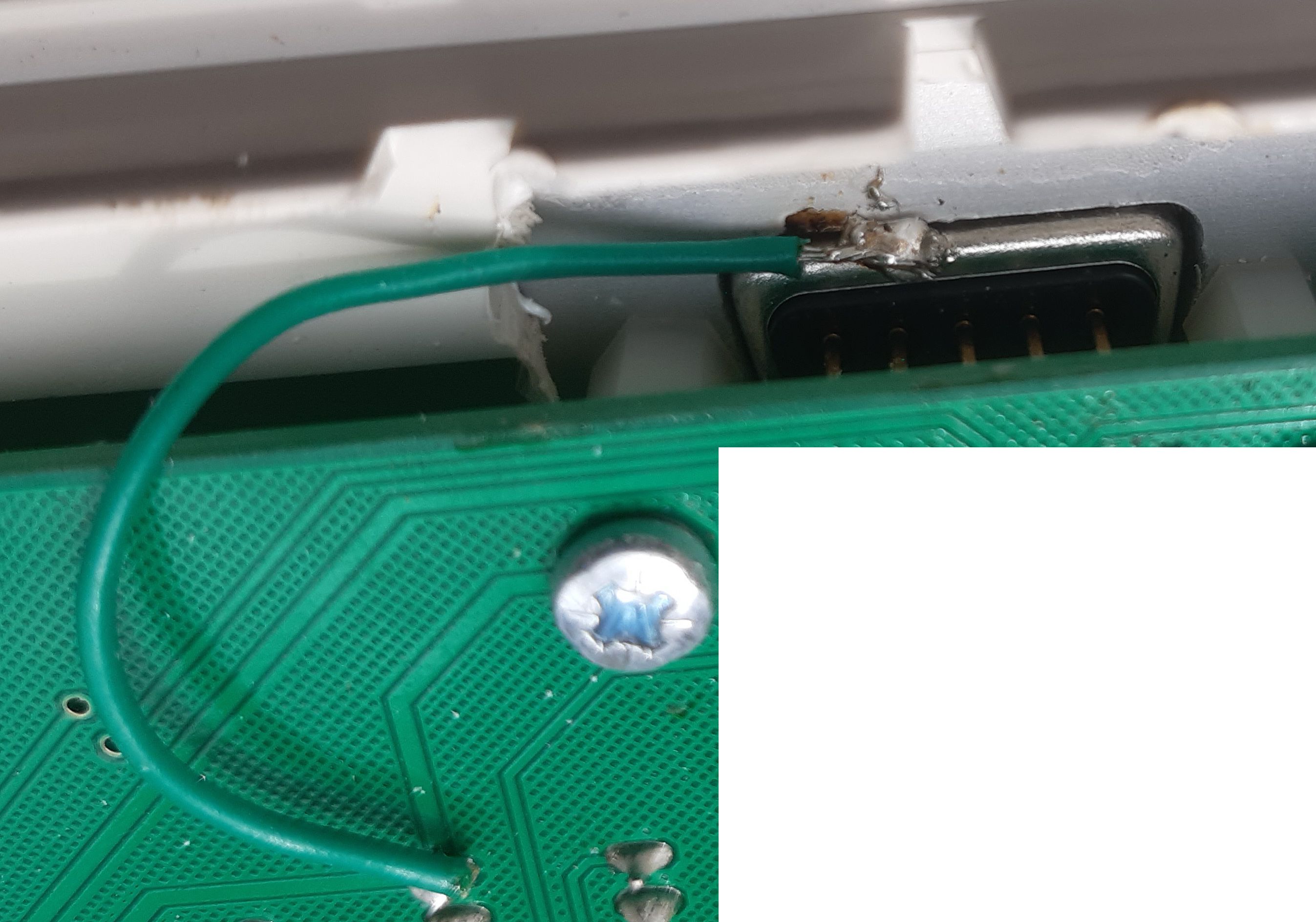
- Solder
the green equipment wire to the underside of the DE9
as shown here and solder the free end into the tag fitted above
- Mount
2x M3x12mm spacers in the remaining mounting holes
on the Main PCB
- Cut
the adhesive strip in to 5 pieces (2x 12cm, 1x 17cm,
2x 6cm) and fit on to the panel mounting face of the
frame
- Sit
the front panel in to the lid and press firmly to
ensure good contact with the adhesive strips
- Offer
the ES34 assembly up to the front panel and use the
2x RS232 bolts to hold the assembly to the front
panel
- Fit
the TouchPad PCB ensuring that the TouchPad header
mates properly with its mating receptacle on the
ES34
- Secure
the TouchPad PCB to the ES34 PCB using the 2x M3x8mm
socket screws
- Mount
the Compartment Panel on to the Base moulding using
4x M3x8mm Taptite screws
- Fit
4x BumpOns onto the Compartment Panel in the recess
above the fixing screws
- Mount
the Base onto The Front moulding and secure using 4x
M3x8mm Taptite screws