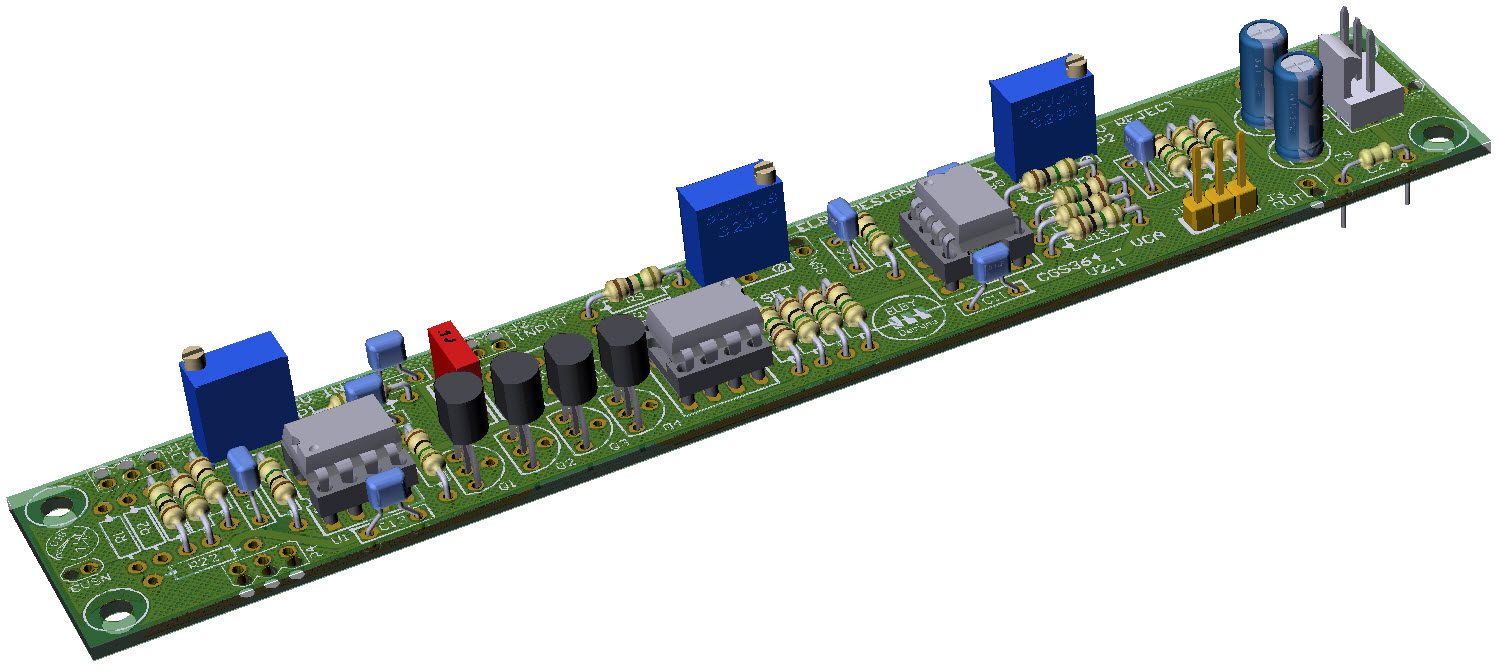
Constructors should refer to the Component Overlays along
with,
the PCB Bill of
Materials for the current value of
all components, and
the General
Construction Notes for general PCB
assembly guidelines.
The SIGNAL inputs are, by default, AC
coupled and so are only suited to audio type
signals. If you wish to control CV type
signals then replace the relevant input
capacitors (C3, C4 and/or C5) with a wire
link, we also recommend changing their jack
colours to BLUE.
The CGS364 requires a matched NPN
transistor pair in the Amplifier Stage at Q5
for optimum performance. Please refer to Dual-Matched
Transistors for further details.
Jumper JP1 allows the output levels
of the module to be reduced so that it can be
used as a basic audio output for connection to
external equipment. Short JP1_1 & JP1_2
for the standard output levels or JP1_2 &
JP1_3 for the reduced level audio output.