Constructors should refer to the PCB Bill of
Materials for the current value of
all components,
and
the General
Construction Notes for general PCB
assembly guidelines.
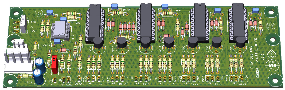
J801 is a dual-footprint component and has both parts shown in the
diagrams. The larger 0.156” connector is still available but we recommend
changing to the smaller 0.1” connector as the gauge of the power wiring from
the CGS391 is a better fit in the crimps for this connector.
J802 is not normally required and should only be installed when stacking the
CGS405 to gain full functionality of the original CGS36 in the same 2” PCB
footprint.
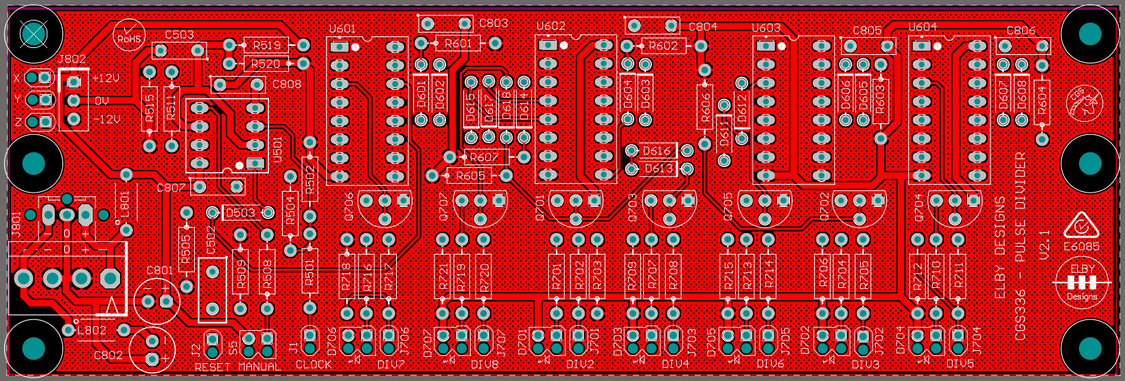
ADDENDUM
A wire link needs to be installed between U601_13 and U601_8.


