 |
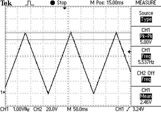
Apply a 100Hz 5VDC TRIANGLE waveform to [IN1] and [IN2]
|
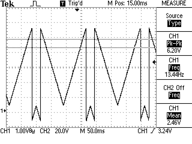 |
Set the [KILL] switch to [K2] and connect a scope to the [UP] output
Adjust the [IN 1] level control until the LED starts flickering
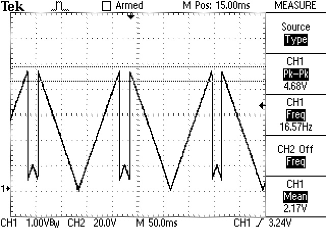
The waveform will develop a 'glitch' as shown at left |
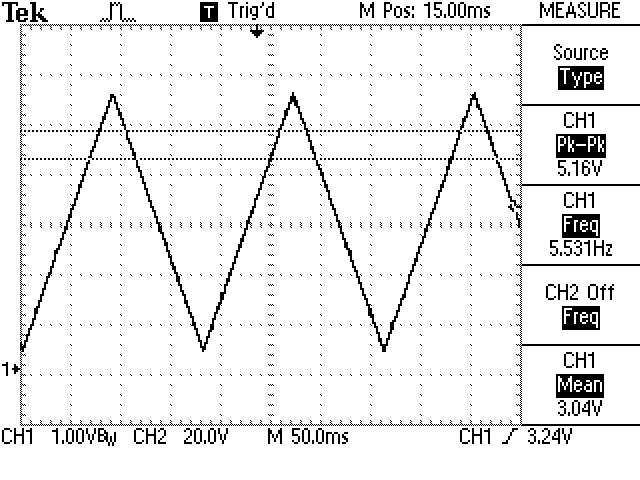 |
Set the [KILL] switch to [K1] and adjust the [IN2] level control until the LED starts flickering
Slowly wind the pot back until the LED just stops flickering
The 'glitch' in the waveform will start to reduce and should be gone at the same time as the LED stops flickering . |
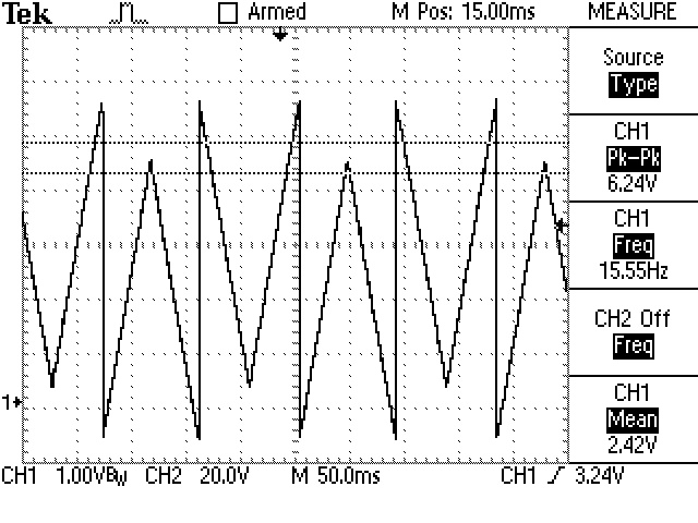 |
Set the [KILL] switch to the centre position where you should see an output simuilar to the shaown at left |
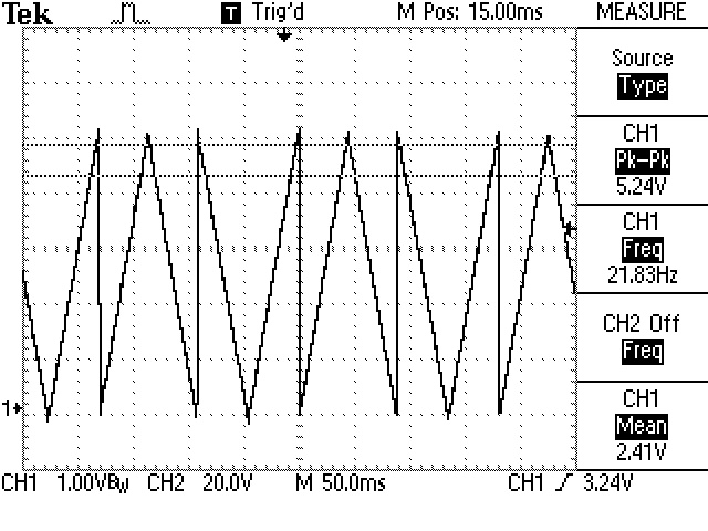 |
Adjust the 'UP' trimpot (P103) until all the bottom points of the waveform all hit 0V |
 |
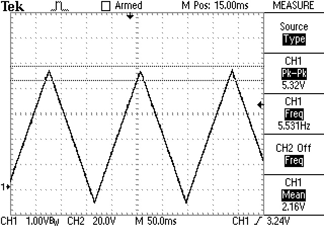
Connect the oscilloscope to the [DOWN] output and disconnect the TRIANGLE from [IN 1]
You should see a waveform similar to that shown at left |
 |
Adjust P105 until the 'glitch' disappears
The waveform should look similar to that shown at left
There will probably be a DC offset as shown here |
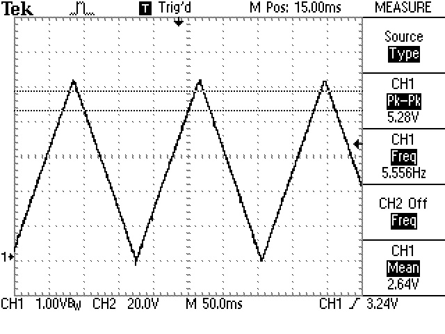 |
Adjust the [DOWN] trimpot (P104) until the bottom of the waveform hits 0V |


