|
|
 |
MIDI-Retrofit-8 Module
|
|

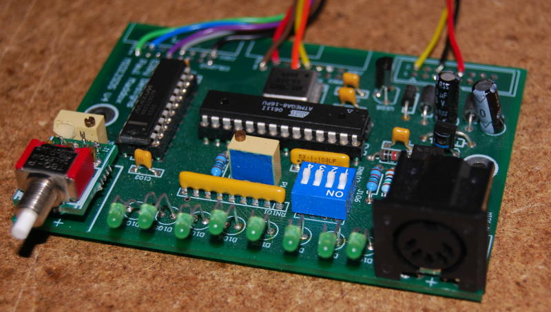
The MIDI-Retrofit-8
started out as a re-release
of the MIDI2SDS from Paul
Maddox and was called MIDI2SDS (X)
Original schematics and circuit details are here MIDI2SDS II Schematic NB: These above items cannot be used with the current ELBY Designs offerings MIDI-Retrofit-8
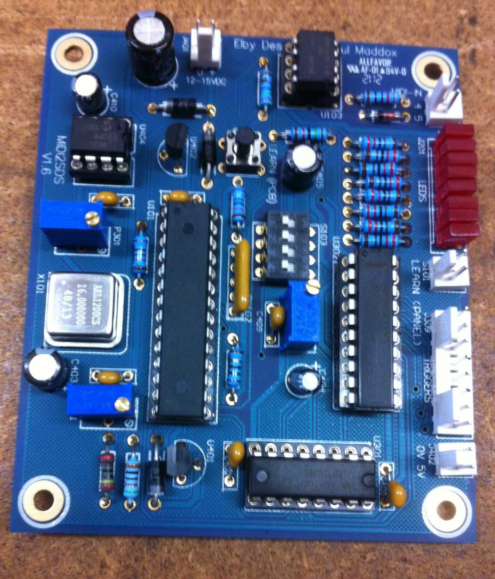
The current revision
of the MIDI-Retrofit-8 utilises the MAX528 8-bit DAC which
allows for a wider
range of output voltages. MIDI-Retrofit-8 supports 2 'trigger modes':-
The logic polarity of the TRIGGER outputs is also selectable:-
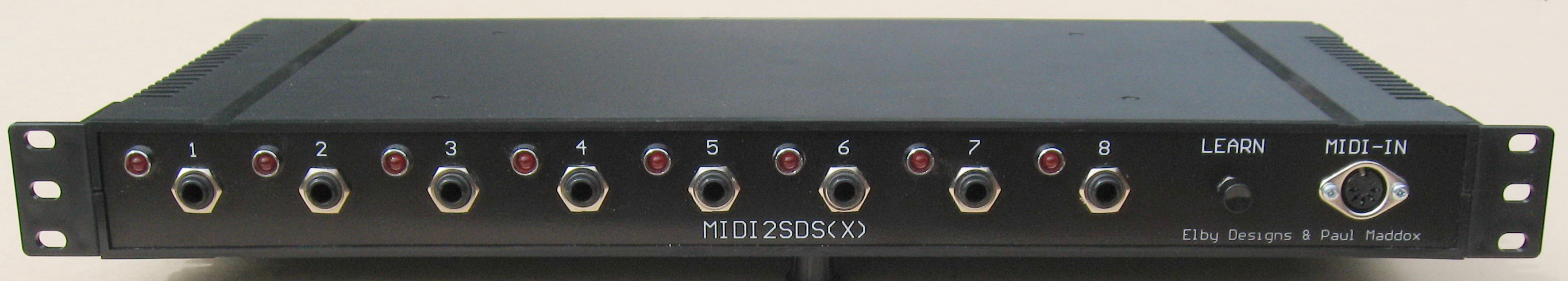
In both cases the maximum amplitude of the TRIGGER output is determined by the VELOCITY value of the respective NOTE ON message as a proportion of the maximum set output voltage. Settings are common to all outputs. Accent Mode MIDI-Retrofit-8 now supports an optional ACCENT Mode. When enabled, the TRIGGER outputs Bill of Materials for MIDI-Retrofit-8 pcb MIDI-Retrofit-8 software (V4.4) Midi-Retrofit-8 is also available as a 3U Euro-Module - see ED103 in the Panther and EuroSerge sections of the shop INSTALLATION OPTIONS The minimal installation option is to mount the MIDI-Retrofit-8 inside the unit to be controlled, wiring the TRIGGER outputs directly to the relevant points on the instrument and connecting to a suitable power supply inside the unit. The MIDI-IN socket being the only item that requires to be mounted on the unit for easy access. This option is suited for installations where the MIDI Note assignments will be set once (or very infrequently). The standard installation optionally brings the LEARN switch out to a user accessible point as well as installing LEDs to indicate the status of each of the TRIGGER outputs. During normal use, the LEDs indicate the status of each TRIGGER output. While in LEARN mode they indicate which channel is being programmed. This is useful if you wish to change the MIDI Note assignments often and/or desire a visual indication of the operation of the MIDI-Retrofit-8. If LED status is required for programming but is not needed for normal operation (or you don't want to mount the LEDs on your unit) the MIDI-Retrofit-8 pcb allows for the LEDs to be mounted on the pcb directly. These, in conjunction with the onboard LEARN switch, allow the user to observe the programming status during the LEARN mode. Installing in to a Roland CR-8000 The MIDI Retrofit-8 being used in a Simmons SDSV courtesy of The SImmons Guy MIDI2SDS(X) (MIDI-Retrofit-8-1U) The
MIDI-Retrofit-8-1U houses the MIDI-Retrofit-8 module in a lightweight
ABS 19" 1U rack
Visit this link for examples of the former MIDI2SDS being used to MIDIfy a drum machine http://www.cykong.com/Synths/Tama TS-305/TamaTS305-MIDI.htm To
implement these retrofits you will need:- These
2 items will provide you with the PCB and all components
needed to dress the PCB.
|
© Copyright 2000. All rights reserved. Revised: February 10, 2026