|

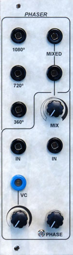
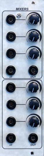
for music synthesizers. The CGS90 Phaser is now DISCONTINUED This module is a variation on the classic Serge Phaser module. From the 1982 catalog: The VC Phaser (PHA) is perhaps the lowest noise and lowest distortion phase shifter available today. As an aid to recreating some of the subtle properties of phase delay in acoustic sounds, three separate outputs are provided with 360 degree, 720 degree, and 1080 degree of voltage controllable phase shift. A MIX output combines the 1080 degree phase shift with the input signal to produce the multiple notch filter effect that is usually associated with phase shifters. The VC Phaser's log-conforming characteristics and the manual and voltage controls enable ultra-smooth, precisely centered sweeps of phase shift for both spatial effects and timbral modification. For high-density systems. a 2'' DUAL PHASER (2PHA) is available. From an early catalog: The Serge MIXER (MIX) is two independent mixers. Each section is a four-in/one-out manual mixer. Three inputs have level control potentiometers and one input is a unity gain (non-attenuated) input. The main output of one section can be connected to the unity gain input of the other section to create larger mixing units. This module can be used as two audio mixers with three variable inputs, or as one mixer with six variable inputs. This module can also be used in combination with other mixers, VCA modules and output modules to provide various mixing functions. A two-inch version of the Mixer is available for high density systems. The mixer presented here is derived from the original R2 mixer, with some concession to later designs. It is inverting, and AC coupled, meaning it is for audio use only. A 741 can be used for the op-amp as per the original design, or a more modern op-amp such as the TL071 can be substituted. There are two of these mixers on the PCB. Note that the raw 360 degree, 720 degree, and 1080 degree do not provide the classic phasing sound. They must be mixed with the incoming signal for this to occur. The MIX output does this onboard with the 1080 degree output. The two MIX mixers provided on the PCB are to allow you to experiment with mixing the signals, both straight and inverted (these mixers are inverting mixers), as well as experimenting with feedback by mixing the signal to be processed with the phase shifted outputs before feeding it into the input of the phaser itself. Feedback experiments require the use of AC coupled mixers such as these to prevent any op-amp offset cascading and driving the unit into distortion. A little on how it works:
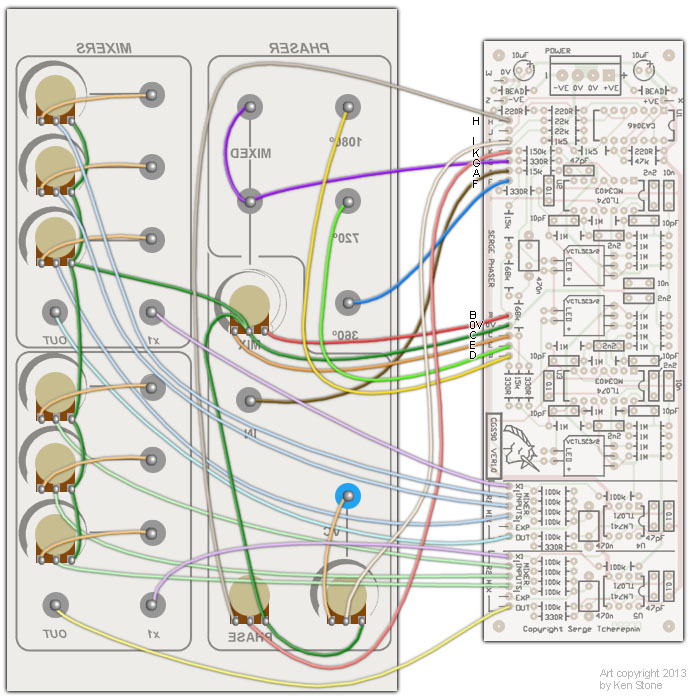
Construction
This is one of those designs where it is possible to experiment with the choice of op-amp used, both in the mixer and the phaser itself. A 741 can be used for the op-amps in the mixers as per the original design, or a more modern op-amp such as the TL071 can be substituted. For the phaser itself, standard footprint op-amps have been used instead of the original RC4136. LM3403 can be used for comparable performance, or something like TL074 can be substituted. It is a good idea to use metal film resistors to help keep the noise floor low. The unit will run on either +/-12 volts or +/-15 volts.
Set UpThere is no set-up. Suggested tests are detailed here. Notes:
Parts list This is a guide only. Parts needed will vary with individual constructor's needs. Article, art & design copyright by Ken Stone |
||||||||||||||||||||||||||||||||||||||||||||||||||